62 Guidelines for planning the electrical installation
Additional data for calculating the rise time and the peak line-to-line voltage
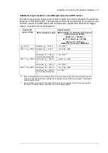
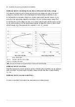
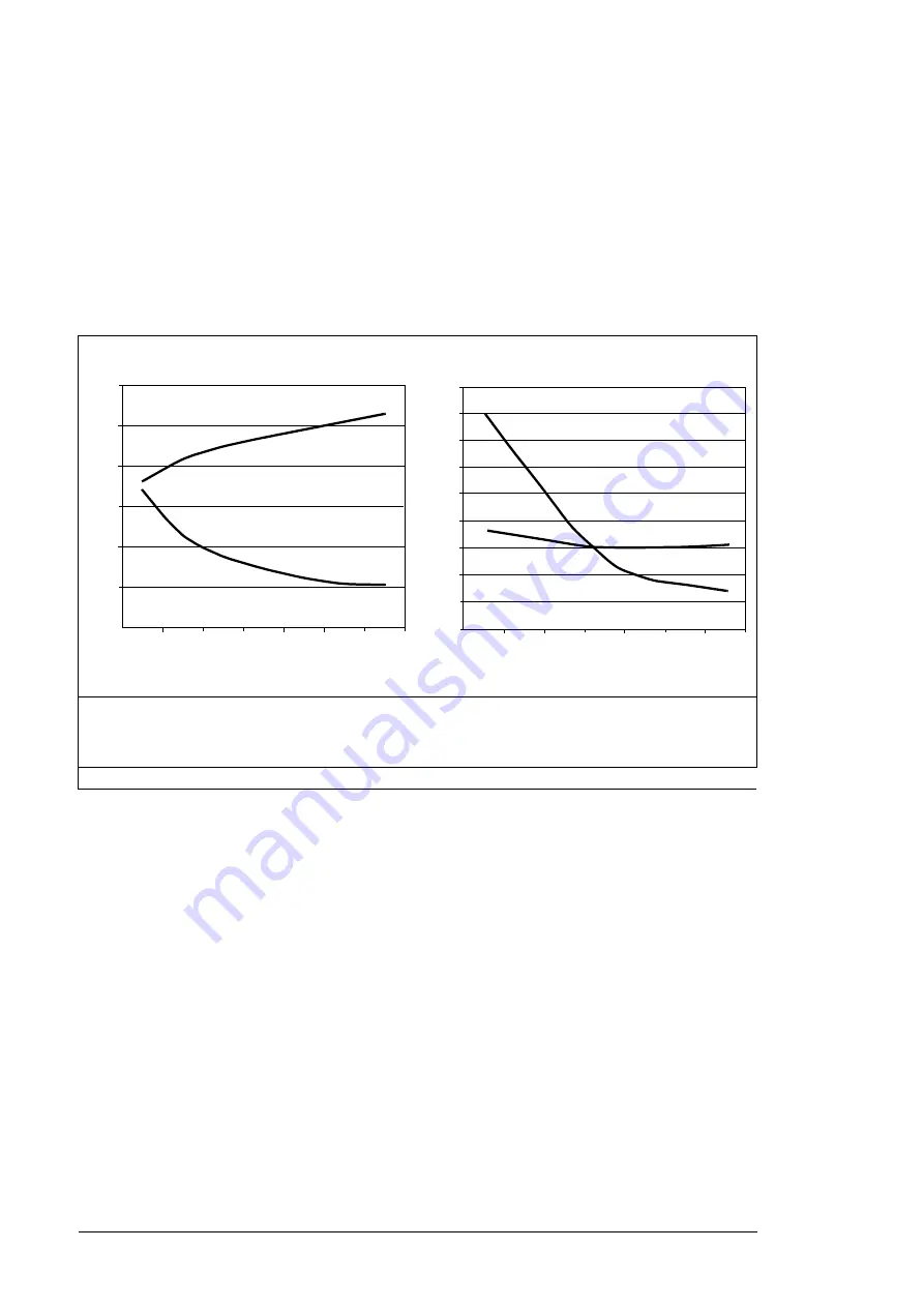
The diagrams below show the relative peak line-to-line voltage and rate of change of
voltage as a function of the motor cable length with and without a d
u
/d
t
filter in use.
To calculate the actual peak voltage for a certain cable length read the relative
Û
LL
/
U
N
value from the appropriate diagram and multiply it by the nominal supply voltage (
U
N
).
To calculate the actual voltage rise time for a certain cable length read the relative values
Û
LL
/
U
N
and (d
u
/d
t
)/U
N
from the appropriate diagram. Multiply the values by the nominal
supply voltage (U
N
) and substitute into equation
t
= 0.8 ·
Û
LL
/(d
u
/d
t
).
Additional note for sine filters
Sine filters protect the motor insulation system. Therefore, the d
u
/d
t
filter can be replaced
with a sine filter. The peak phase-to-phase voltage with the sine filter is approximately
1.5 ·
U
N
.
Additional note for common mode filters
Common mode filter is included in the standard drive module delivery.
Drive with d
u
/d
t
filter
Drive without d
u
/d
t
filter
I
Motor cable length
Û
LL
/
U
N
Relative peak line-to-line voltage
d
u
/d
t
/U
N
Relative d
u
/d
t
value
Note
: ÛLL and du/dt values are approximately 20% higher with resistor braking.
100
200
300
0.0
0.5
1.0
1.5
2.0
2.5
3.0
l
(m)
du/dt
UN
-------------(1/
s)
Û
LL
/
U
N
Û
LL
/
U
N
l
(m)
du/dt
UN
-------------(1/
s)
1.0
2.0
5.0
4.0
3.0
1.5
2.5
3.5
4.5
100
200
300
5.5
Summary of Contents for ACS880-07XT Series
Page 1: ...ABB industrial drives Hardware manual ACS880 07XT drives 400 to 1200 kW ...
Page 4: ......
Page 12: ...12 ...
Page 20: ...20 Safety instructions ...
Page 26: ...26 Introduction to the manual ...
Page 54: ...54 Mechanical installation ...
Page 89: ...Electrical installation 89 PE 11 8 4 9 11 ...
Page 94: ...94 Electrical installation ...
Page 112: ...112 Fault tracing ...
Page 123: ...Maintenance 123 5 6 7 ...
Page 124: ...124 Maintenance 8 10 9 ...
Page 126: ...126 Maintenance 6 5 4 ...
Page 127: ...Maintenance 127 9 8 7 ...
Page 128: ...128 Maintenance 12 11 10 ...
Page 149: ...Dimensions 149 Dimension drawing examples Frame 2 R11 R10 with brake chopper ...
Page 150: ...150 Dimensions Frame 2 R11 R10 without brake chopper ...
Page 153: ...Dimensions 153 Location of input terminals ACS880 07XT 12 pulse ...
Page 154: ...154 Dimensions Location of output terminals ACS880 07XT R10 with du dt ...
Page 155: ...Dimensions 155 Location of output terminals ACS880 07XT R10 without du dt ...
Page 156: ...156 Dimensions Location of output terminals ACS880 07XT R11 with du dt ...
Page 157: ...Dimensions 157 Location of output terminals ACS880 07XT R11 without du dt ...
Page 158: ...158 Dimensions Location of PE terminals ACS880 07XT ...
Page 159: ...Dimensions 159 Location of resistor terminals ACS880 07XT R10 ...
Page 160: ...160 Dimensions Location of resistor terminals ACS880 07XT R11 ...
Page 168: ...www abb com drives www abb com drivespartners 3ABD00043579 Rev C EN 2018 01 01 Contact us ...


