Electrical installation 79
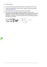
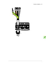
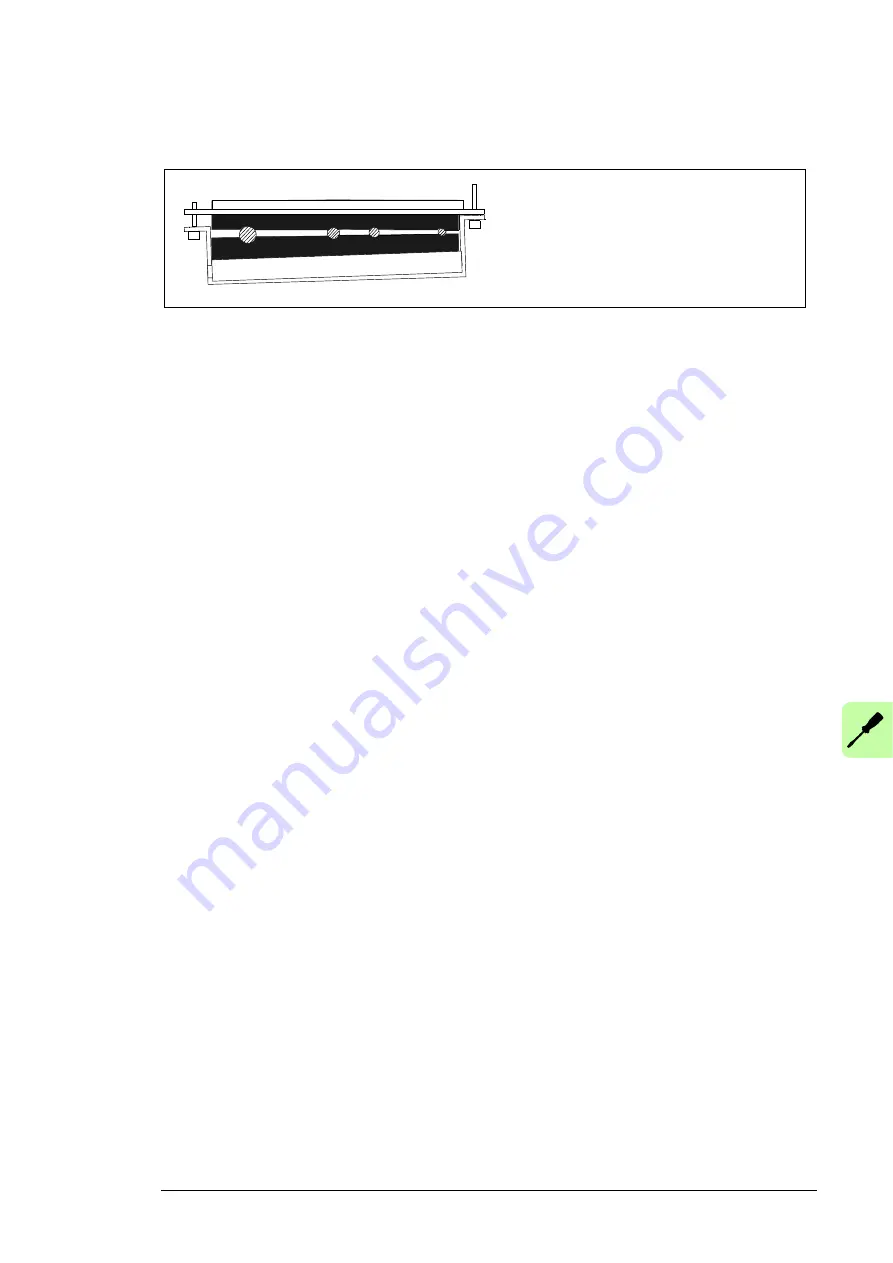
5. Arrange the bunches according to size from thickest to the thinnest between the EMI
conductive cushions.
6. If more than one cable go through a grommet, seal the grommet by applying Loctite
5221 (catalogue number 25551) inside the grommet.
Routing the control cables inside the cabinet
Use the existing trunking in the cabinet wherever possible. Use sleeving if cables are laid
against sharp edges. When running cables to or from the swing-out frame, leave enough
slack at the hinge to allow the frame to open fully.
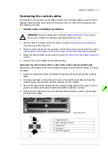
Connecting to the control unit (A41)
Connect the conductors to the appropriate terminals of the control unit or terminal block
X504 (L504).
Connect the inner twisted pair shields and all separate grounding wires to the grounding
clamps below the control unit.
The drawing below represents a drive with additional I/O terminal block (L504).
Without the block, the grounding is made the same way.
Notes:
•
Do not ground the outer shield of the cable here since it is grounded at the lead-
through.
•
Keep any signal wire pairs twisted as close to the terminals as possible. Twisting the
wire with its return wire reduces disturbances caused by inductive coupling.
At the other end of the cable, leave the shields unconnected or ground them indirectly via
a high-frequency capacitor with a few nanofarads, eg. 3.3 nF / 630 V. The shield can also
be grounded directly at both ends if they are in the same ground line with no significant
voltage drop between the end points.
Summary of Contents for ACS880-07XT Series
Page 1: ...ABB industrial drives Hardware manual ACS880 07XT drives 400 to 1200 kW ...
Page 4: ......
Page 12: ...12 ...
Page 20: ...20 Safety instructions ...
Page 26: ...26 Introduction to the manual ...
Page 54: ...54 Mechanical installation ...
Page 89: ...Electrical installation 89 PE 11 8 4 9 11 ...
Page 94: ...94 Electrical installation ...
Page 112: ...112 Fault tracing ...
Page 123: ...Maintenance 123 5 6 7 ...
Page 124: ...124 Maintenance 8 10 9 ...
Page 126: ...126 Maintenance 6 5 4 ...
Page 127: ...Maintenance 127 9 8 7 ...
Page 128: ...128 Maintenance 12 11 10 ...
Page 149: ...Dimensions 149 Dimension drawing examples Frame 2 R11 R10 with brake chopper ...
Page 150: ...150 Dimensions Frame 2 R11 R10 without brake chopper ...
Page 153: ...Dimensions 153 Location of input terminals ACS880 07XT 12 pulse ...
Page 154: ...154 Dimensions Location of output terminals ACS880 07XT R10 with du dt ...
Page 155: ...Dimensions 155 Location of output terminals ACS880 07XT R10 without du dt ...
Page 156: ...156 Dimensions Location of output terminals ACS880 07XT R11 with du dt ...
Page 157: ...Dimensions 157 Location of output terminals ACS880 07XT R11 without du dt ...
Page 158: ...158 Dimensions Location of PE terminals ACS880 07XT ...
Page 159: ...Dimensions 159 Location of resistor terminals ACS880 07XT R10 ...
Page 160: ...160 Dimensions Location of resistor terminals ACS880 07XT R11 ...
Page 168: ...www abb com drives www abb com drivespartners 3ABD00043579 Rev C EN 2018 01 01 Contact us ...


