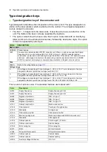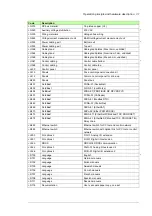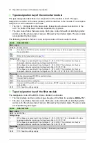
36 Guidelines for planning electrical installation
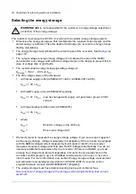
Selecting the energy storage
WARNING!
ABB is not responsible for the customer ‘s energy storage selection or
protection of the energy storage.
The customer must equip the DC/DC converter with a suitable energy storage system:
•
Dimension the energy storage so that it withstands the required current cycles and the
stored energy is sufficient. Take the depth of discharge into account in energy storage
lifetime calculations.
•
The energy storage must withstand the current ripple of the converter. See
page
•
The output voltage (energy storage voltage) is not allowed to exceed the DC/DC
converter DC bus voltage. Add sufficient voltage margin in the design to prevent this in
case of voltage dips or grid faults.
•
The recommended energy storage operating voltage is:
U
storage
= 150 V … 80% of
U
DC
•
The DC voltage values of the drives are:
•
with diode supply units (ACS880-307 +A003, ACS880-307 +A018):
•
with IGBT supply units (ACS880-207) typically
•
with regenerative rectifier units (ACS880-907):
•
where
•
We recommend to measure the energy storage voltage. If you use a super capacitor
as the energy storage, voltage measurement is obligatory. If the converter is equipped
with the BAMU voltage/current measurement unit (G442), the converter
measures its output voltage (and thus also the ES voltage) automatically. You do not
need any additional measurement for the converter. If there is no BAMU, you must
arrange the voltage measurement separately, and send the measured value to the
converter control program, eg, via a fieldbus communication (if in use), or by some
other means. For more information, see section
Energy storage voltage measurement
and estimation
and parameter description in
ACS880 DC/DC converter control
program firmware manual
(3AXD50000024671 [English]).
•
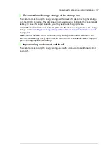
The energy storage must have a disconnecting device and contactor. See
Disconnection of energy storage at the storage end
and
U
DC
= 1.35 ×
U
AC
U
DC
= 1.41 ×
U
AC
(can be changed with supply unit parameter group 123 DC
volt ref)
U
DC
= 1.35 ×
U
AC
U
DC
=
Drive DC voltage (in the DC bus)
U
AC
=
Drive input voltage (AC)
Summary of Contents for ACS880-1607
Page 1: ...ABB industrial drives Hardware manual ACS880 1607 DC DC converter units ...
Page 4: ......
Page 12: ...12 Introduction to the manual ...
Page 34: ...34 Mechanical installation ...
Page 40: ...40 Guidelines for planning electrical installation ...
Page 52: ...52 Electrical installation ...
Page 68: ...68 Start up ...
Page 80: ...80 Maintenance 7 3 4 5 6 ...
Page 82: ...82 Maintenance 3 4 5 6 7 8 9 9 ...
Page 85: ...Maintenance 85 12 Install and tighten the two screws 10 11 12 ...
Page 92: ...92 Maintenance 3 6 4 5 4 7a 7b 7b ...
Page 93: ...Maintenance 93 9 8 8 10 11 ...
Page 96: ...96 Maintenance 4 8 6 7 5 3 ...
Page 97: ...Maintenance 97 9 ...
Page 118: ...118 Dimensions Dimension drawings Frame 1 R8i bottom cable entry ...
Page 119: ...Dimensions 119 Frame 1 R8i top cable entry ...
Page 122: ...www abb com drives www abb com drivespartners 3AXD50000023644 Rev B EN 2017 01 30 Contact us ...

