Operation principle and hardware description 17
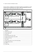
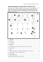
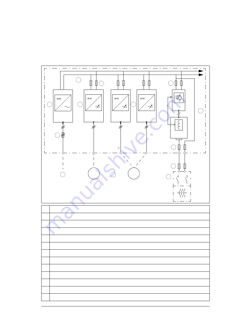
Overview diagram of a drive with a converter unit
This diagram shows a possible application of a converter unit in an example system. The
DC/DC converter unit includes a DC/DC converter module and a filter module. The
customer must equip the energy storage with fuses and a device for disconnecting the
storage from the DC/DC converter. The disconnecting device does not belong to the
ACS880-1607 unit delivery.
Description
1. AC
supply
2. Input
(AC)
fuses
3. Supply
module
4.
DC bus (-, +)
5.
Inverter DC fuses (with or without a DC switch/disconnector, F286)
6. Inverter
modules
7. Motors
8.
DC fuses (DC bus side, with or without a DC switch/disconnector, F286)
9.
DC/DC converter unit (converter and filter modules)
10. Output
DC
fuses
11. Energy storage DC fuses
12. Energy storage with disconnector and contactor.
2
1
3
t°
M
3~
M
3~
6
6
9
10
4
5
7
8
3
12
11
_
+
Summary of Contents for ACS880-1607
Page 1: ...ABB industrial drives Hardware manual ACS880 1607 DC DC converter units ...
Page 4: ......
Page 12: ...12 Introduction to the manual ...
Page 34: ...34 Mechanical installation ...
Page 40: ...40 Guidelines for planning electrical installation ...
Page 52: ...52 Electrical installation ...
Page 68: ...68 Start up ...
Page 80: ...80 Maintenance 7 3 4 5 6 ...
Page 82: ...82 Maintenance 3 4 5 6 7 8 9 9 ...
Page 85: ...Maintenance 85 12 Install and tighten the two screws 10 11 12 ...
Page 92: ...92 Maintenance 3 6 4 5 4 7a 7b 7b ...
Page 93: ...Maintenance 93 9 8 8 10 11 ...
Page 96: ...96 Maintenance 4 8 6 7 5 3 ...
Page 97: ...Maintenance 97 9 ...
Page 118: ...118 Dimensions Dimension drawings Frame 1 R8i bottom cable entry ...
Page 119: ...Dimensions 119 Frame 1 R8i top cable entry ...
Page 122: ...www abb com drives www abb com drivespartners 3AXD50000023644 Rev B EN 2017 01 30 Contact us ...

