22 Operation principle and hardware description
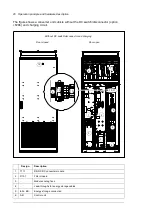
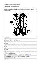
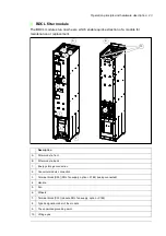
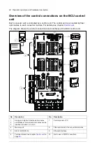
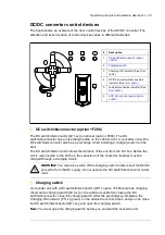
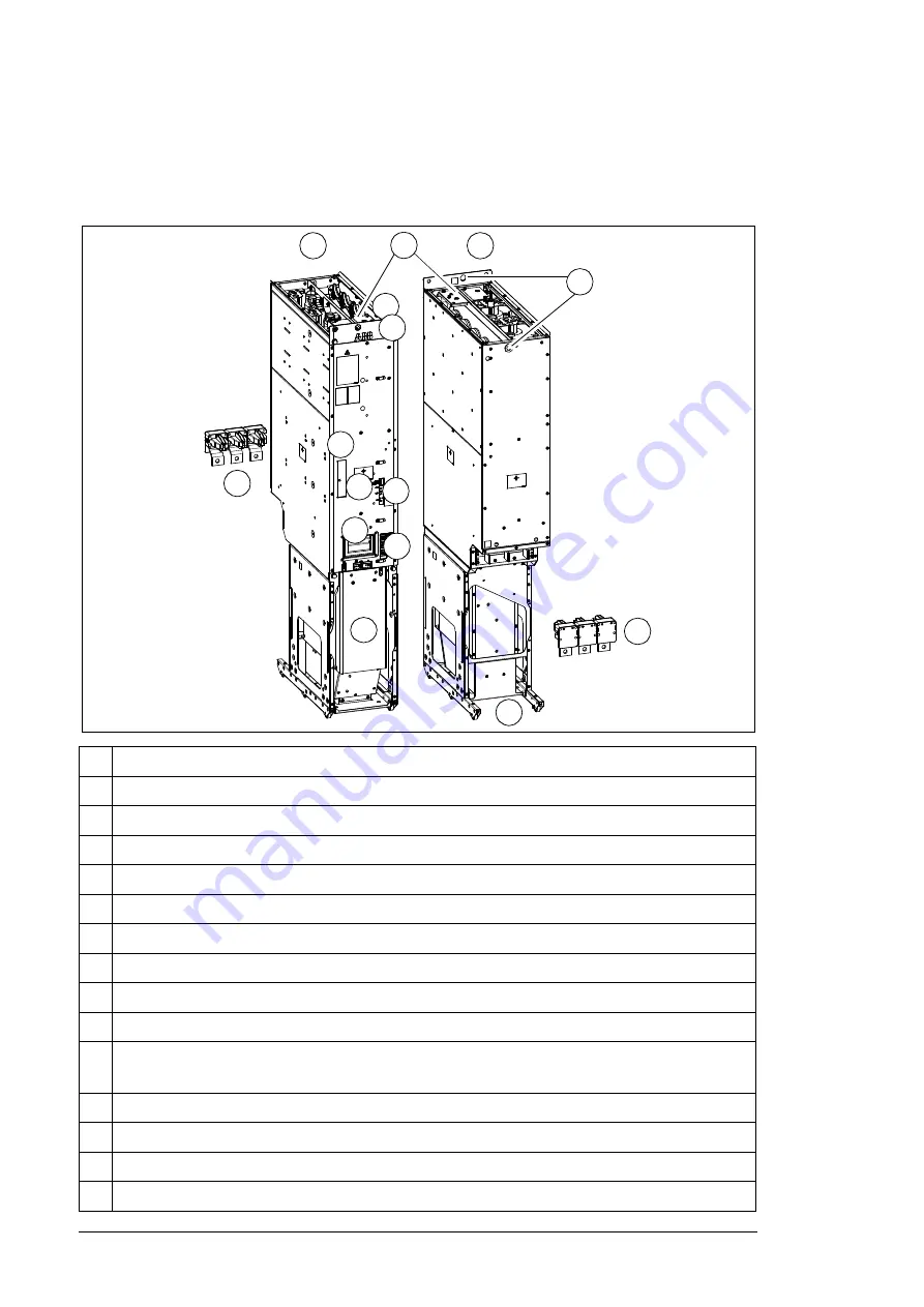
R8i DC/DC converter module
The converter modules run on wheels, which, along with the quick connector, enable quick
extraction of a module for maintenance or replacement.The figure shows the layout of the
converter module.
Description
A
DC/DC converter module, frame size R8i, front
B
DC/DC converter module, frame size R8i, back
1.
Common DC bus connection
2. Handle
3.
Fiber optic connectors of the module (wired to the control unit)
4. Fan
5.
Quick connector (BDCL connection) (The counterpart fastened to the cabinet behind the module.)
6. Wheels
7.
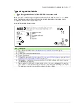
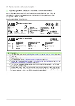
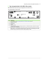
Type designation label of the module
8.
Terminal block [X50] (power supply for internal boards and module heating element, C183;
DOL fan supply, C188)
9.
Connector [X53]. For more information on the connectors, see chapter
.
10. The unpainted grounding point (PE) between module frame and cabinet frame
11. Circuit board compartment fan
12. Lifting
eyes.
A
B
5
5
2
3
4
1
6
7
8
9
10
11
12
Summary of Contents for ACS880-1607
Page 1: ...ABB industrial drives Hardware manual ACS880 1607 DC DC converter units ...
Page 4: ......
Page 12: ...12 Introduction to the manual ...
Page 34: ...34 Mechanical installation ...
Page 40: ...40 Guidelines for planning electrical installation ...
Page 52: ...52 Electrical installation ...
Page 68: ...68 Start up ...
Page 80: ...80 Maintenance 7 3 4 5 6 ...
Page 82: ...82 Maintenance 3 4 5 6 7 8 9 9 ...
Page 85: ...Maintenance 85 12 Install and tighten the two screws 10 11 12 ...
Page 92: ...92 Maintenance 3 6 4 5 4 7a 7b 7b ...
Page 93: ...Maintenance 93 9 8 8 10 11 ...
Page 96: ...96 Maintenance 4 8 6 7 5 3 ...
Page 97: ...Maintenance 97 9 ...
Page 118: ...118 Dimensions Dimension drawings Frame 1 R8i bottom cable entry ...
Page 119: ...Dimensions 119 Frame 1 R8i top cable entry ...
Page 122: ...www abb com drives www abb com drivespartners 3AXD50000023644 Rev B EN 2017 01 30 Contact us ...

