Operation principle and hardware description 25
DC/DC converter control devices
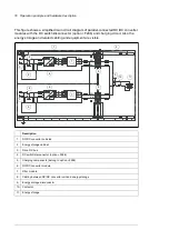
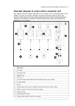
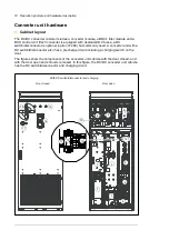
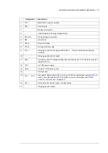
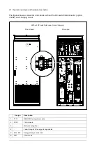
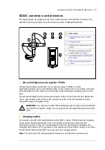
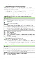
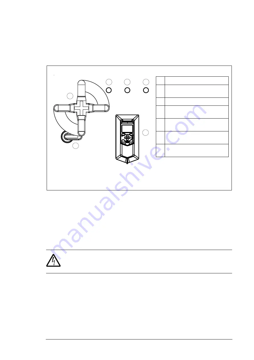
The figure shows an example of the door control devices of the DC/DC converter. The
selection and exact location of control devices varies in different deliveries.
DC switch/disconnector (F286)
The DC switch/disconnector [Q11.xx] is optional (F286). The DC
switch/disconnector has an operating handle on the cabinet door. A converter unit with a
DC switch/disconnector also has a precharge circuit including a charging switch on the
door.
The DC switch/disconnector allows the isolation of the unit from the DC bus. Before the
unit is reconnected to the DC bus, the capacitors of the converter modules must be
charged through a charging circuit.
WARNING!
You must also switch off the charging switch to disconnect the DC/DC
converter from the DC supply. Do not operate the DC switch/disconnector under
load.
Charging switch
A converter unit with a DC switch/disconnector ([Q11], F286) also has charging
circuit and a charging switch [Q10.x] on the cubicle door. Before closing the DC
switch/disconnector, close the charging switch. After the precharging completes, the
Charging OK indicator [P11.x] (green) on the cabinet door illuminates, and you can close
the DC switch/disconnector [Q11.xx], and open the charging switch.
Note:
You must open the charging switch before you can start the converter unit.
#
Description
1.
DC switch/disconnector (option
+F286)
2.
3.
Charging OK indicator (See
4. DC/DC
converter
disconnected
indicator (See
5.
Load disconnected indicator (See
.)
6.
ACS-AP-x control panel (option
+J400)
1
2
3
6
4
5
Summary of Contents for ACS880-1607
Page 1: ...ABB industrial drives Hardware manual ACS880 1607 DC DC converter units ...
Page 4: ......
Page 12: ...12 Introduction to the manual ...
Page 34: ...34 Mechanical installation ...
Page 40: ...40 Guidelines for planning electrical installation ...
Page 52: ...52 Electrical installation ...
Page 68: ...68 Start up ...
Page 80: ...80 Maintenance 7 3 4 5 6 ...
Page 82: ...82 Maintenance 3 4 5 6 7 8 9 9 ...
Page 85: ...Maintenance 85 12 Install and tighten the two screws 10 11 12 ...
Page 92: ...92 Maintenance 3 6 4 5 4 7a 7b 7b ...
Page 93: ...Maintenance 93 9 8 8 10 11 ...
Page 96: ...96 Maintenance 4 8 6 7 5 3 ...
Page 97: ...Maintenance 97 9 ...
Page 118: ...118 Dimensions Dimension drawings Frame 1 R8i bottom cable entry ...
Page 119: ...Dimensions 119 Frame 1 R8i top cable entry ...
Page 122: ...www abb com drives www abb com drivespartners 3AXD50000023644 Rev B EN 2017 01 30 Contact us ...

