26 Operation principle and hardware description
WARNING!
You must also switch off the charging switch to disconnect the DC/DC
converter from the DC supply.
Door lights
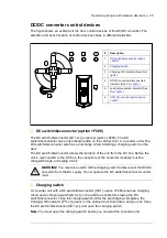
The load disconnected indicator ([P13.x], white) is always installed on the cabinet door.
The Charging OK indicator ([P11.x], green) and DC/DC converter disconnected indicator
([P12.x], white) are installed when the DC switch/disconnector (F286) is selected.
The customer must connect the load disconnected indicator to the disconnecting device of
the energy storage. For more information on the disconnecting devices, see
of energy storage at the storage end
on page
.
When the white lamps are on, the DC/DC converter is disconnected from both the DC bus
and the energy storage.
ACS-AP-x control panel (J400)
One control panel is required for the commissioning of an ACS880 drive system, even if
the Drive composer PC tool is used. With the control panel, you can:
•
start and stop the converter unit
•
view and reset the fault and warning messages, and view the fault history
•
view actual signals
•
change parameter settings
•
change between local and external control.
The control panel can be mounted on the cabinet door using a DPMP-01 mounting
platform (available separately).
For the instructions on the use of the panel, see
ACX-AP-x assistant control panels user's
manual
(3AUA0000085685 [English]). For the parameter settings and control modes, see
ACS880 DC/DC converter control program firmware manual
(3AXD50000024671
[English]).
PC connection
There is a USB connector on the front of the panel that can be used to connect a PC to the
drive. When a PC is connected to the control panel, the control panel keypad is disabled.
See also section
on page
Fieldbus control
You can control the converter unit through a fieldbus interface if the unit is equipped with
an optional fieldbus adapter (for example, K454), and when you have configured
the control program for the fieldbus control with the parameters. For more information, see
ACS880 DC/DC converter control program firmware manual
(3AXD50000024671
[English]).
Summary of Contents for ACS880-1607
Page 1: ...ABB industrial drives Hardware manual ACS880 1607 DC DC converter units ...
Page 4: ......
Page 12: ...12 Introduction to the manual ...
Page 34: ...34 Mechanical installation ...
Page 40: ...40 Guidelines for planning electrical installation ...
Page 52: ...52 Electrical installation ...
Page 68: ...68 Start up ...
Page 80: ...80 Maintenance 7 3 4 5 6 ...
Page 82: ...82 Maintenance 3 4 5 6 7 8 9 9 ...
Page 85: ...Maintenance 85 12 Install and tighten the two screws 10 11 12 ...
Page 92: ...92 Maintenance 3 6 4 5 4 7a 7b 7b ...
Page 93: ...Maintenance 93 9 8 8 10 11 ...
Page 96: ...96 Maintenance 4 8 6 7 5 3 ...
Page 97: ...Maintenance 97 9 ...
Page 118: ...118 Dimensions Dimension drawings Frame 1 R8i bottom cable entry ...
Page 119: ...Dimensions 119 Frame 1 R8i top cable entry ...
Page 122: ...www abb com drives www abb com drivespartners 3AXD50000023644 Rev B EN 2017 01 30 Contact us ...

