44 Electrical installation
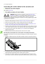
Connecting the control cables for the converter unit
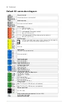
Default I/O connection diagram
See chapter
.
Connection procedure of control cables
WARNING!
Repeat the steps described in section
on page
. The complete safety instructions are given in
Safety instructions for ACS880 multidrive cabinets and modules
(3AUA0000102301 [English]). Ignoring the instructions can cause physical injury or death,
or damage to the equipment.
1. Repeat the steps described in section
2. Open the door of the DC/DC converter cubicle and remove the shrouding.
3. Run the control cables into the cubicle as described in section
shields of the control cables at the cabinet lead-through
below.
4. Route the control cables to the control connection terminals. Use the existing trunking
in the cabinet wherever possible. Use sleeving if cables are laid against sharp edges.
5. Connect the control cables. See chapter
and the circuit diagrams
delivered with the drive.
6. Refit any shrouds removed earlier and close the door of the cubicle.
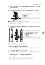
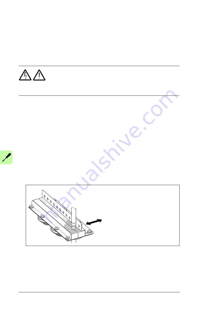
Grounding the outer shields of the control cables at the cabinet lead-through
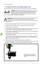
Ground the outer shields of all control cables 360 degrees at the EMI conductive cushions
as follows:
1. Slacken the tightening screws of the EMI conductive cushions and pull the cushions
apart.
2. Cut adequate holes to the rubber grommets in the lead-through plate and lead the
cables through the grommets and the cushions into the cabinet.
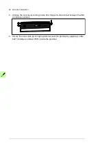
3. Strip off the cable plastic sheath above the lead-through plate just enough to make
sure that the connection of the bare shield and the EMI conductive cushions is proper.
Summary of Contents for ACS880-1607
Page 1: ...ABB industrial drives Hardware manual ACS880 1607 DC DC converter units ...
Page 4: ......
Page 12: ...12 Introduction to the manual ...
Page 34: ...34 Mechanical installation ...
Page 40: ...40 Guidelines for planning electrical installation ...
Page 52: ...52 Electrical installation ...
Page 68: ...68 Start up ...
Page 80: ...80 Maintenance 7 3 4 5 6 ...
Page 82: ...82 Maintenance 3 4 5 6 7 8 9 9 ...
Page 85: ...Maintenance 85 12 Install and tighten the two screws 10 11 12 ...
Page 92: ...92 Maintenance 3 6 4 5 4 7a 7b 7b ...
Page 93: ...Maintenance 93 9 8 8 10 11 ...
Page 96: ...96 Maintenance 4 8 6 7 5 3 ...
Page 97: ...Maintenance 97 9 ...
Page 118: ...118 Dimensions Dimension drawings Frame 1 R8i bottom cable entry ...
Page 119: ...Dimensions 119 Frame 1 R8i top cable entry ...
Page 122: ...www abb com drives www abb com drivespartners 3AXD50000023644 Rev B EN 2017 01 30 Contact us ...

