232 The Safe torque off function
Competence
The maintenance and proof test activities of the safety function must be carried out by a
competent person with adequate expertise and knowledge of the safety function as well as
functional safety, as required by IEC 61508-1 clause 6.
Fault tracing
The indications given during the normal operation of the Safe torque off function are
selected by inverter control program parameter 31.22.
The diagnostics of the Safe torque off function cross-compare the status of the two STO
channels. In case the channels are not in the same state, a fault reaction function is
performed and the inverter trips on an “STO hardware failure” fault. An attempt to use the
STO in a non-redundant manner, for example activating only one channel, will trigger the
same reaction.
See the firmware manual of the inverter control program for the indications generated by
the inverter, and for details on directing fault and warning indications to an output on the
control unit for external diagnostics.
Any failures of the Safe torque off function must be reported to ABB.
Safety data
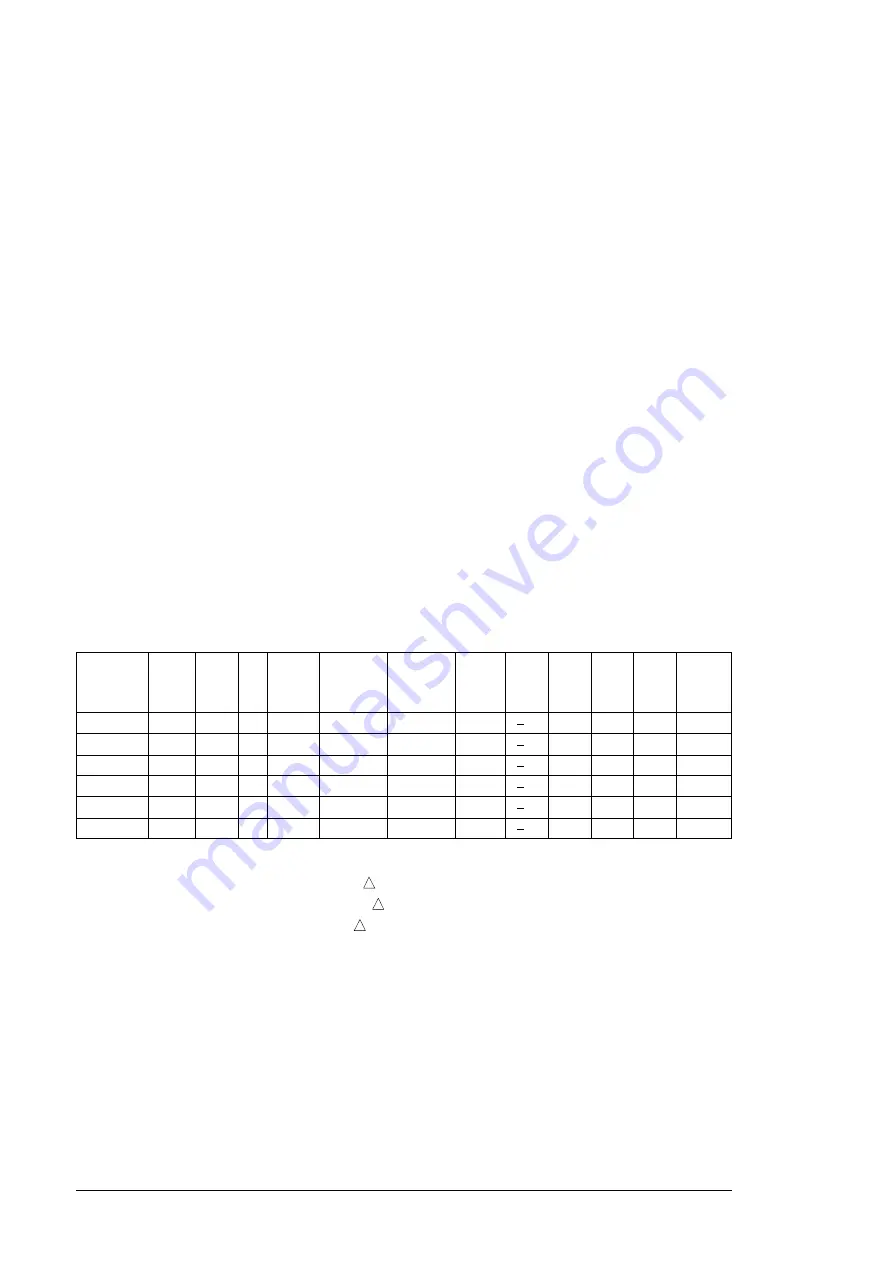
The safety data for the Safe torque off function is given below.
Note:
The safety data is calculated for redundant use, and does not apply if both STO
channels are not used.
•
The following temperature profile is used in safety value calculations:
•
670 on/off cycles per year with
T
= 71.66 °C
•
1340 on/off cycles per year with
T
= 61.66 °C
•
30 on/off cycles per year with
T
= 10.0 °C
•
32 °C board temperature at 2.0% of time
•
60 °C board temperature at 1.5% of time
•
85 °C board temperature at 2.3% of time.
•
The STO is a type B safety component as defined in IEC 61508-2.
•
Relevant failure modes:
•
The STO trips spuriously (safe failure)
•
The STO does not activate when requested
A fault exclusion on the failure mode “short circuit on printed circuit board” has been
made (EN 13849-2, table D.5). The analysis is based on an assumption that one
failure occurs at one time. No accumulated failures have been analyzed.
•
STO reaction time (shortest detectable break): 1 ms
Frame size
SIL/
SILCL
SC
PL
SFF
PFH
D
(T
1
= 20 a)
PFD
(T
1
= 2 a)
MTTF
d
DC
Cat.
HFT
CCF
Lifetime
(%)
(1/h)
(a)
(%)
(a)
R8i
3
3
e
>99
4.74E-11
4.23E-07
27325
>90
3
1
80
20
2×R8i
3
3
e
>99
5.57E-11
4.98E-07
19607
>90
3
1
80
20
3×R8i
3
3
e
>99
6.39E-11
5.74E-07
15295
>90
3
1
80
20
4×R8i
3
3
e
>99
7.22E-11
6.49E-07
12540
>90
3
1
80
20
5×R8i
3
3
e
>99
8.05E-11
7.24E-07
10626
>90
3
1
80
20
6×R8i
3
3
e
>99
8.87E-11
7.99E-07
9220
>90
3
1
80
20
Summary of Contents for ACS880-17
Page 1: ...ABB industrial drives Hardware manual ACS880 37 drives ...
Page 3: ......
Page 4: ......
Page 6: ......
Page 16: ...16 ...
Page 30: ...30 Introduction to the manual ...
Page 70: ...70 Mechanical installation ...
Page 105: ...Electrical installation 105 4 5 3 6 7 ...
Page 107: ...Electrical installation 107 5 6 4 3 ...
Page 108: ...108 Electrical installation 7 8 8 ...
Page 109: ...Electrical installation 109 9 10 ...
Page 111: ...Electrical installation 111 2 360 grounding detail a b b 1 5 a 11 b a PE 10 7 5 6 8 ...
Page 117: ...Electrical installation 117 PE 11 8 4 9 11 ...
Page 134: ...134 Control units of the drive ...
Page 140: ...140 Start up ...
Page 142: ...142 Fault tracing ...
Page 154: ...154 Maintenance 4 5 6 7 8 6 10 10 ...
Page 162: ...162 Maintenance 5 6 3 4 7 ...
Page 163: ...Maintenance 163 6 8 7 11 10 9 ...
Page 167: ...Maintenance 167 3 4b 4a 4b 8 ...
Page 185: ...Technical data 185 Declaration of Conformity ...
Page 186: ...186 Technical data ...
Page 196: ...196 Dimensions Dimension drawing examples Frame 1 R8i 1 R8i ...
Page 197: ...Dimensions 197 Frame 1 R8i 1 R8i top cable entry exit H351 H353 ...
Page 198: ...198 Dimensions Frame 1 R8i 1 R8i with brake choppers and resistors D150 D151 ...
Page 199: ...Dimensions 199 Frame 1 R8i 1 R8i with sine output filter E206 ...
Page 200: ...200 Dimensions Frame 2 R8i 2 R8i eg ACS880 37 1110A 3 IP22 ...
Page 201: ...Dimensions 201 Frame 2 R8i 2 R8i eg ACS880 37 1210A 3 IP54 ...
Page 204: ...204 Dimensions Frame 2 R8i 2 R8i with main breaker F255 and top entry top exit H351 H353 1 2 ...
Page 205: ...Dimensions 205 Frame 2 R8i 2 R8i with main breaker F255 and top entry top exit H351 H353 2 2 ...
Page 206: ...206 Dimensions Frame 3 R8i 3 R8i 1 2 ...
Page 207: ...Dimensions 207 Frame 3 R8i 3 R8i 2 2 ...
Page 208: ...208 Dimensions Frame 3 R8i 3 R8i with common motor terminal cubicle H359 1 2 ...
Page 209: ...Dimensions 209 Frame 3 R8i 3 R8i with common motor terminal cubicle H359 2 2 ...
Page 217: ...Dimensions 217 Sine filter E206 cubicle 1000 mm top cable exit ...
Page 221: ...Dimensions 221 Cubicle width 400 mm top cable exit Cubicle width 600 mm bottom cable exit ...
Page 222: ...222 Dimensions Cubicle width 600 mm top cable exit ...
Page 234: ...234 The Safe torque off function ...
Page 244: ...www abb com drives www abb com drivespartners 3AXD50000020437 Rev A EN 2015 02 06 Contact us ...


