128 Control units of the drive
Notes:
The wire size accepted by all screw terminals (for both stranded and solid wire) is
0.5 … 2.5 mm
2
(24…12 AWG). The torque is 0.5 N·m (5 lbf·in).
1)
See section
(page
).
2)
See chapter
(page
).
3)
0 = Acceleration/deceleration ramps defined by parameters 23.12/23.13 in use.
1 = Acceleration/deceleration ramps defined by parameters 23.14/23.15 in use.
4)
Constant speed 1 is defined by parameter 22.26.
5)
See section
(page
6)
Total load capacity of these outputs is 4.8 W (200 mA at 24 V) minus the power taken by
DIO1 and DIO2.
7)
Determines whether DICOM is separated from DIOGND (ie. common reference for
digital inputs floats; in practice, selects whether the digital inputs are used in current
sinking or sourcing mode). See also
.
DICOM = DIOGND
ON: DICOM connected to DIOGND. OFF: DICOM and DIOGND
separate.
8)
Current [0(4)…20 mA,
R
in
= 100 ohm] or voltage [0(2)…10 V,
R
in
> 200 kohm] input
selected by switch
AI1
. Change of setting requires reboot of control unit.
9)
Current [0(4)…20 mA,
R
in
= 100 ohm] or voltage [0(2)…10 V,
R
in
> 200 kohm] input
selected by switch
AI2
. Change of setting requires reboot of control unit.
External power supply for the control unit (XPOW)
The BCU-x2 is powered from a 24 V DC, 2 A supply through terminal block XPOW. A
second supply can be connected to the same terminal block for redundancy.
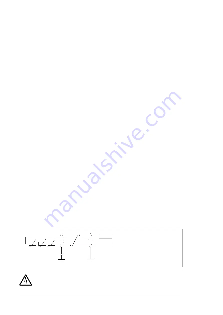
DI6 as a PTC sensor input
PTC sensors can be connected to this input for motor temperature measurement as
follows. The sum of the sensor resistances must not exceed the threshold resistance of
the digital input at normal motor operating temperature. Do not connect both ends of the
cable shield directly to ground. If a capacitor cannot be used at one end, leave that end of
the shield unconnected. See the firmware manual for parameter settings.
Note
: PTC sensors can alternatively be connected to FEN-xx encoder interface module.
WARNING!
As the inputs pictured above are not insulated according to
IEC 60664, the connection of the motor temperature sensor requires double or
reinforced insulation between motor live parts and the sensor. If the assembly
does not fulfill the requirement, the I/O board terminals must be protected against contact
T
3.3 nF
> 630 V AC
PTC
DI6
+24VD
T
T
“0” > 4 kohm
“1” < 1.5 kohm
I
max
= 5 mA
Summary of Contents for ACS880-17
Page 1: ...ABB industrial drives Hardware manual ACS880 37 drives ...
Page 3: ......
Page 4: ......
Page 6: ......
Page 16: ...16 ...
Page 30: ...30 Introduction to the manual ...
Page 70: ...70 Mechanical installation ...
Page 105: ...Electrical installation 105 4 5 3 6 7 ...
Page 107: ...Electrical installation 107 5 6 4 3 ...
Page 108: ...108 Electrical installation 7 8 8 ...
Page 109: ...Electrical installation 109 9 10 ...
Page 111: ...Electrical installation 111 2 360 grounding detail a b b 1 5 a 11 b a PE 10 7 5 6 8 ...
Page 117: ...Electrical installation 117 PE 11 8 4 9 11 ...
Page 134: ...134 Control units of the drive ...
Page 140: ...140 Start up ...
Page 142: ...142 Fault tracing ...
Page 154: ...154 Maintenance 4 5 6 7 8 6 10 10 ...
Page 162: ...162 Maintenance 5 6 3 4 7 ...
Page 163: ...Maintenance 163 6 8 7 11 10 9 ...
Page 167: ...Maintenance 167 3 4b 4a 4b 8 ...
Page 185: ...Technical data 185 Declaration of Conformity ...
Page 186: ...186 Technical data ...
Page 196: ...196 Dimensions Dimension drawing examples Frame 1 R8i 1 R8i ...
Page 197: ...Dimensions 197 Frame 1 R8i 1 R8i top cable entry exit H351 H353 ...
Page 198: ...198 Dimensions Frame 1 R8i 1 R8i with brake choppers and resistors D150 D151 ...
Page 199: ...Dimensions 199 Frame 1 R8i 1 R8i with sine output filter E206 ...
Page 200: ...200 Dimensions Frame 2 R8i 2 R8i eg ACS880 37 1110A 3 IP22 ...
Page 201: ...Dimensions 201 Frame 2 R8i 2 R8i eg ACS880 37 1210A 3 IP54 ...
Page 204: ...204 Dimensions Frame 2 R8i 2 R8i with main breaker F255 and top entry top exit H351 H353 1 2 ...
Page 205: ...Dimensions 205 Frame 2 R8i 2 R8i with main breaker F255 and top entry top exit H351 H353 2 2 ...
Page 206: ...206 Dimensions Frame 3 R8i 3 R8i 1 2 ...
Page 207: ...Dimensions 207 Frame 3 R8i 3 R8i 2 2 ...
Page 208: ...208 Dimensions Frame 3 R8i 3 R8i with common motor terminal cubicle H359 1 2 ...
Page 209: ...Dimensions 209 Frame 3 R8i 3 R8i with common motor terminal cubicle H359 2 2 ...
Page 217: ...Dimensions 217 Sine filter E206 cubicle 1000 mm top cable exit ...
Page 221: ...Dimensions 221 Cubicle width 400 mm top cable exit Cubicle width 600 mm bottom cable exit ...
Page 222: ...222 Dimensions Cubicle width 600 mm top cable exit ...
Page 234: ...234 The Safe torque off function ...
Page 244: ...www abb com drives www abb com drivespartners 3AXD50000020437 Rev A EN 2015 02 06 Contact us ...


