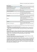
or inductively to other conductors in the control cable and form a risk of malfunction in other
parts of the system.
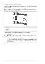
Install the protective component as close to the inductive load as possible. Do not install
protective components at the relay outputs.
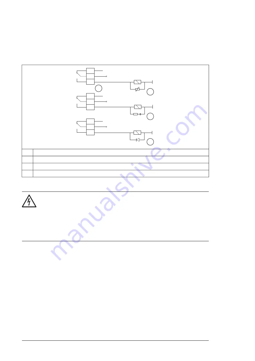
230 V AC
230 V AC
+ 24 V DC
1
2
3
4
Relay output
1
Varistor
2
RC filter
3
Diode
4
■
Implementing a motor temperature sensor connection
WARNING!
IEC 60664 and IEC 61800-5-1 require double or reinforced insulation between
live parts and accessible parts when:
•
the accessible parts are not conductive, or
•
the accessible parts are conductive, but not connected to the protective earth.
Obey this requirement when you plan the connection of the motor temperature
sensor to the drive.
You have these implementation alternatives:
104 Guidelines for planning the electrical installation
Summary of Contents for ACS880-37
Page 1: ... ABB INDUSTRIAL DRIVES ACS880 37 drives 45 400 kW 60 450 hp Hardware manual ...
Page 2: ......
Page 4: ......
Page 26: ...26 ...
Page 83: ...Mechanical installation 83 10 ...
Page 84: ...84 ...
Page 126: ... B055 a X504 126 Electrical installation ...
Page 144: ...144 ...
Page 150: ...150 ...
Page 152: ...152 ...
Page 160: ... 160 Maintenance ...
Page 196: ... 196 Maintenance ...
Page 232: ...R8 IP22 UL Type 1 and option B054 IP42 UL Type 1 Filtered 232 Dimension drawings ...
Page 233: ...R8 IP54 UL Type 12 option B055 option C129 Dimension drawings 233 ...
Page 235: ...R8 IP22 UL Type 1 and IP42 UL Type 1 Filtered option B054 option E206 Dimension drawings 235 ...
Page 236: ...R8 IP22 UL Type 1 option E202 236 Dimension drawings ...
Page 237: ...R11 IP22 UL Type 1 and IP42 UL Type 1 Filtered option B054 Dimension drawings 237 ...
Page 238: ...R11 IP54 UL Type 12 option B055 238 Dimension drawings ...
Page 240: ...R11 IP54 UL Type 12 option B055 option C128 240 Dimension drawings ...
Page 241: ...R11 IP54 UL Type 12 option B055 option C129 Dimension drawings 241 ...
Page 242: ...R11 IP54 UL Type 12 option B055 options C129 H350 H352 242 Dimension drawings ...
Page 243: ...R11 IP22 UL Type 1 and IP42 UL Type 1 Filtered option B054 option D150 Dimension drawings 243 ...
Page 245: ...R11 IP22 UL Type 1 and IP42 UL Type 1 Filtered option B054 option E206 Dimension drawings 245 ...
Page 246: ...R11 IP22 UL Type 1 option E202 246 Dimension drawings ...
Page 267: ... Declaration of conformity The Safe torque off function 267 ...
Page 268: ...268 The Safe torque off function ...
Page 280: ...280 ...


