3.
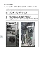
For R8 bottom entry of cables:
•
If there is a mounting plate above the fan, loosen the four screws and pull out the
plate. Unplug the connectors and remove the plate.
•
If there is no mounting plate, but a shroud above the fan, undo the four screws and
remove the shroud.
•
Remove the “door fan”. See section
Replacing the cabinet “door fan” (page 158)
•
Remove the plastic shroud in front of input terminals.
For R8 top entry of cables:
•
Unplug the connectors, loosen the four screws and lift off the top mounting plate.
•
Remove the plastic shroud in front of input terminals.
For R11 bottom entry of cables:
•
If there is a mounting plate/two plates above the fan, loosen the four screws of the
plate and pull out the plate/s. Unplug the connectors and remove the plate/s.
•
If there is no mounting plate/s, but a shroud/s above the fan, undo the four screws
and remove the shroud/s.
•
Remove the “door fan”. See section
Replacing the cabinet “door fan” (page 158)
•
Marine drives (C121): Undo the three M6 screws on the left side of the
swing-out frame.
•
Undo the two screws and open the swing-out frame or remove the shroud if there
is no swing-out frame.
•
Remove the plastic shroud in front of input terminals.
For R11 top entry of cables:
•
Marine drives (C121): Undo the three M6 screws on the left side of the
swing-out frame.
•
Undo the two screws and open the swing-out frame or remove the shroud if there
is no swing-out frame.
•
Marine drives (C121): Undo the four M6 screws and remove the support
in front of top fuse plate.
•
Unplug the connectors, loosen the four M6 screws and remove the top fuse plate.
4.
Plan cable access and mark the conduit plate accordingly for the input and output power
and control cables.
5.
Remove the conduit plate from the drive cabinet and cut holes as needed for the conduit
connections. Note: Never cut metal in or around an equipment cabinet. Metal debris
can cause damage to electrical equipment and hazardous conditions.
6.
Reinstall the conduit plate to cabinet and connect all electrical conduits as needed to
conduit plate. Do not leave any open holes at the top of the cabinet.
7.
Run the motor power cables and separate ground cable (if present) from the motor to
cabinet.
8.
Connect the motor power cable shields and separate ground cable (if present) to the
ground bar at the top of the cabinet for top entry and at the bottom of the cabinet if
bottom entry (H350).
9.
Connect the motor phase conductors to the output power terminals U2, V2 and W2.
118 Electrical installation
Summary of Contents for ACS880-37
Page 1: ... ABB INDUSTRIAL DRIVES ACS880 37 drives 45 400 kW 60 450 hp Hardware manual ...
Page 2: ......
Page 4: ......
Page 26: ...26 ...
Page 83: ...Mechanical installation 83 10 ...
Page 84: ...84 ...
Page 126: ... B055 a X504 126 Electrical installation ...
Page 144: ...144 ...
Page 150: ...150 ...
Page 152: ...152 ...
Page 160: ... 160 Maintenance ...
Page 196: ... 196 Maintenance ...
Page 232: ...R8 IP22 UL Type 1 and option B054 IP42 UL Type 1 Filtered 232 Dimension drawings ...
Page 233: ...R8 IP54 UL Type 12 option B055 option C129 Dimension drawings 233 ...
Page 235: ...R8 IP22 UL Type 1 and IP42 UL Type 1 Filtered option B054 option E206 Dimension drawings 235 ...
Page 236: ...R8 IP22 UL Type 1 option E202 236 Dimension drawings ...
Page 237: ...R11 IP22 UL Type 1 and IP42 UL Type 1 Filtered option B054 Dimension drawings 237 ...
Page 238: ...R11 IP54 UL Type 12 option B055 238 Dimension drawings ...
Page 240: ...R11 IP54 UL Type 12 option B055 option C128 240 Dimension drawings ...
Page 241: ...R11 IP54 UL Type 12 option B055 option C129 Dimension drawings 241 ...
Page 242: ...R11 IP54 UL Type 12 option B055 options C129 H350 H352 242 Dimension drawings ...
Page 243: ...R11 IP22 UL Type 1 and IP42 UL Type 1 Filtered option B054 option D150 Dimension drawings 243 ...
Page 245: ...R11 IP22 UL Type 1 and IP42 UL Type 1 Filtered option B054 option E206 Dimension drawings 245 ...
Page 246: ...R11 IP22 UL Type 1 option E202 246 Dimension drawings ...
Page 267: ... Declaration of conformity The Safe torque off function 267 ...
Page 268: ...268 The Safe torque off function ...
Page 280: ...280 ...

