■
Grounding the motor cable shield at the motor end
For minimum radio-frequency interference, ground the cable shield 360 degrees at the cable
entry of the motor terminal box.
Connecting the control cables
See chapter
for the default I/O connections of the drive control unit
(with the ACS880 primary control program). The default I/O connections can be different
with some hardware options, see the circuit diagrams delivered with the drive for the actual
wiring. For other control programs, see their firmware manuals.
1.
Run the control cables into the drive module cubicle.
2.
Route the control cables as described in section
Routing the control cables inside the
3.
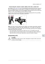
For connecting the external control cables to the drive control unit, see section
Connecting the external control cables to the drive control unit (page 127)
4.
For connecting the external control cables to the option terminals, see the circuit diagrams
delivered with the drive.
■
Routing the control cables inside the cabinet
Routing the control cables inside the cabinet
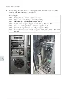
Use the existing trunking in the cabinet wherever possible. Use sleeving if cables are laid
against sharp edges. When running cables to or from a swing-out frame, leave enough
slack at the hinge to allow the frame to open fully.
Frame R8
1.
Stop the drive and do the steps in section
Electrical safety precautions (page 17)
before
you start the work.
2.
Open the cabinet door.
3.
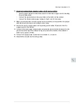
If there is a mounting plate above the fan, loosen the four screws and pull out the plate.
Unplug the connectors and remove the plate.
If there is no mounting plate, but instead a shroud above the "door fan", undo the four
screws and remove the shroud.
4.
Remove the "door fan”. See section
Replacing the cabinet “door fan” (page 158)
120 Electrical installation
Summary of Contents for ACS880-37
Page 1: ... ABB INDUSTRIAL DRIVES ACS880 37 drives 45 400 kW 60 450 hp Hardware manual ...
Page 2: ......
Page 4: ......
Page 26: ...26 ...
Page 83: ...Mechanical installation 83 10 ...
Page 84: ...84 ...
Page 126: ... B055 a X504 126 Electrical installation ...
Page 144: ...144 ...
Page 150: ...150 ...
Page 152: ...152 ...
Page 160: ... 160 Maintenance ...
Page 196: ... 196 Maintenance ...
Page 232: ...R8 IP22 UL Type 1 and option B054 IP42 UL Type 1 Filtered 232 Dimension drawings ...
Page 233: ...R8 IP54 UL Type 12 option B055 option C129 Dimension drawings 233 ...
Page 235: ...R8 IP22 UL Type 1 and IP42 UL Type 1 Filtered option B054 option E206 Dimension drawings 235 ...
Page 236: ...R8 IP22 UL Type 1 option E202 236 Dimension drawings ...
Page 237: ...R11 IP22 UL Type 1 and IP42 UL Type 1 Filtered option B054 Dimension drawings 237 ...
Page 238: ...R11 IP54 UL Type 12 option B055 238 Dimension drawings ...
Page 240: ...R11 IP54 UL Type 12 option B055 option C128 240 Dimension drawings ...
Page 241: ...R11 IP54 UL Type 12 option B055 option C129 Dimension drawings 241 ...
Page 242: ...R11 IP54 UL Type 12 option B055 options C129 H350 H352 242 Dimension drawings ...
Page 243: ...R11 IP22 UL Type 1 and IP42 UL Type 1 Filtered option B054 option D150 Dimension drawings 243 ...
Page 245: ...R11 IP22 UL Type 1 and IP42 UL Type 1 Filtered option B054 option E206 Dimension drawings 245 ...
Page 246: ...R11 IP22 UL Type 1 option E202 246 Dimension drawings ...
Page 267: ... Declaration of conformity The Safe torque off function 267 ...
Page 268: ...268 The Safe torque off function ...
Page 280: ...280 ...


