background image

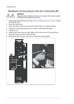
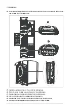
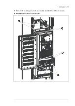
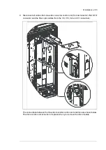
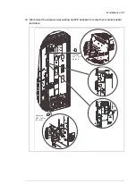
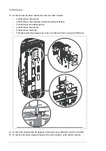
10. Unplug the connector and remove the fan or remove the shroud if there is no fan.

Maintenance 173

Summary of Contents for ACS880-37

Page 1: ... ABB INDUSTRIAL DRIVES ACS880 37 drives 45 400 kW 60 450 hp Hardware manual ...

Page 2: ......

Page 3: ...ACS880 37 drives 45 400 kW 60 450 hp Hardware manual Table of contents 1 Safety instructions 4 Mechanical installation 6 Electrical installation 9 Start up 3AXD50000035159 Rev G EN EFFECTIVE 2020 03 25 ...

Page 4: ......

Page 5: ...d option code 28 Quick installation commissioning and operation flowchart 28 Terms and abbreviations 29 Related manuals 3 Operation principle and hardware description 31 Contents of this chapter 31 Operation principle 32 Single line circuit diagram of the drive 32 Single line diagram of R8 33 Single line diagram of R11 34 Block diagram of the drive with brake options D150 and D151 35 Line side con...

Page 6: ...heater with external supply option G300 52 Cabinet lighting option G301 52 Terminals for external control voltage option G307 53 Output for motor space heater option G313 53 Ready Run Fault lights options G327 G329 53 Halogen free wiring and materials option G330 53 V meter with selector switch option G334 53 A meter in one phase option G335 53 Wire markings 53 Standard wire markings 53 Additional...

Page 7: ...Miscellaneous 79 Cable duct in the floor below the cabinet 79 Arc welding 79 Air inlet through the bottom of cabinet option C128 80 Air outlet duct on the cabinet roof option C130 80 Calculating the required static pressure difference 82 Lifting lugs and bars 82 Certificate of conformity 82 Declaration of Conformity 5 Guidelines for planning the electrical installation 85 Contents of this chapter ...

Page 8: ...rmal overload 100 Protecting the drive against ground faults 100 Residual current device compatibility 100 Implementing the emergency stop function 100 Implementing the Safe torque off function 100 Implementing an ATEX certified motor thermal protection 101 Implementing the Prevention of unexpected start up function 101 Implementing the functions provided by the FSO xx safety functions module 102 ...

Page 9: ...rol cables inside the cabinet 120 Routing the control cables inside the cabinet 120 Frame R8 123 Frame R11 127 Connecting the external control cables to the drive control unit 127 Connecting a PC 129 Installing option modules 129 Mechanical installation of I O extension fieldbus adapter and pulse encoder interface modules 129 Installation of an FSO xx safety functions module beside the ZCU 12 cont...

Page 10: ...e drive module main fan frame R8 161 Replacing the drive module main fans frame R11 163 Replacing the LCL filter module fan frame R11 164 Replacing the auxiliary cooling fan of the drive module frame R8 165 Replacing the auxiliary cooling fans of the drive module frame R11 167 Frame R8 Replacing the IP54 UL Type 12 roof fan and chopper option D150 cubicle fan G101 2 168 Frame R11 with options B055...

Page 11: ...Derating 205 Surrounding air temperature derating 206 Altitude derating 207 Deratings for special settings in the drive control program 211 Fuses IEC 213 Fuses UL 214 Dimensions and weights 214 Dimensions and weights of sine filter cabinet option E206 215 Free space requirements 216 Cooling data noise 217 Sine output filter data 218 Typical cable sizes 219 Tightening torques 219 Electrical connect...

Page 12: ...1 R11 IP54 UL Type 12 option B055 option C129 242 R11 IP54 UL Type 12 option B055 options C129 H350 H352 243 R11 IP22 UL Type 1 and IP42 UL Type 1 Filtered option B054 option D150 244 R11 IP22 UL Type 1 and IP42 UL Type 1 Filtered option B054 options D150 D151 245 R11 IP22 UL Type 1 and IP42 UL Type 1 Filtered option B054 option E206 246 R11 IP22 UL Type 1 option E202 247 Location and size of powe...

Page 13: ...efault brake circuit components ABB chopper and ABB resistor 270 Calculating the maximum allowed braking power for a custom duty cycle ABB chopper and ABB resistor 270 Selecting the default brake circuit components ABB brake chopper and custom resistor 271 Selecting custom resistors 272 Calculating the maximum allowed braking power for a custom duty cycle ABB chopper and custom resistor 272 Exampl...

Page 14: ... resistor types 277 Ratings for the factory installed brake choppers and ABB brake resistors 278 Ratings for factory installed brake choppers and custom resistors 278 DC fuses 279 Terminals and cable entry data of factory installed chopper resistor cubicles Further information 14 Table of contents ...

Page 15: ...you how to prevent the danger Notes draw attention to a particular condition or fact or give information on a subject The manual uses these warning symbols WARNING Electricity warning tells about hazards from electricity which can cause injury or death or damage to the equipment WARNING General warning tells about conditions other than those caused by electricity which can cause injury or death or...

Page 16: ... to the wall when necessary Do not stand or walk on the cabinet roof Make sure that nothing presses against the roof side or back plates or door Do not store anything on the roof while the drive is in operation Beware of hot surfaces Some parts such as heatsinks of power semiconductors and brake resistors remain hot for a while after disconnection of the electrical supply Vacuum clean the area aro...

Page 17: ...drive for example Safe torque off or emergency stop validate them at start up See separate instructions for the safety circuits Beware of hot air exiting from the air outlets Do not cover the air inlet or outlet when the drive is running Note If you select an external source for the start command and it is on the drive will start immediately after fault reset unless you configure the drive for pul...

Page 18: ...her means Disconnect any dangerous external voltages from the control circuits After you disconnect power from the drive always wait 5 minutes to let the intermediate circuit capacitors discharge before you continue 3 Protect any other energized parts in the work location against contact 4 Take special precautions when close to bare conductors 5 Measure that the installation is de energized If the...

Page 19: ... Measuring the voltage Make sure that the voltage between the drive input power terminals L1 L2 L3 and the grounding PE busbar is close to 0 V R11 R8 L1 L2 L3 PE L1 L2 L3 PE Safety instructions 19 ...

Page 20: ... close to 0 V The measuring holes in the shroud of the standard drive are shown below nstructions ame R11 Make sure that the voltage of the drive AC busbars between the drive dule and the LCL filter and the grounding PE busbar are close to 0 V asuring holes of the standard drive in the shroud are shown below PE AC 20 Safety instructions ...

Page 21: ...Make sure that the voltage between the drive DC busbars and and the grounding PE busbar is close to 0 V R11 R8 DC DC DC DC DC DC DC Safety instructions 21 ...

Page 22: ... powered With the doors open a risk of a potentially fatal electric shock arc flash or high energy arc blast exists Make sure that the electrical power network motor generator and environmental conditions agree with the drive data Do not do insulation or voltage withstand tests on the drive If you have a cardiac pacemaker or other electronic medical device keep away from the area near motor drive ...

Page 23: ...s WARNING Use a grounding wrist band when you handle printed circuit boards Do not touch the boards unnecessarily The boards contain components sensitive to electrostatic discharge Grounding These instructions are for all personnel who are responsible for the grounding of the drive WARNING Obey these instructions If you ignore them injury or death or equipment malfunction can occur and electromagn...

Page 24: ...peration There are electromagnetic fields present which can interfere with the function of such devices This can cause a health hazard Give a stop command to the drive before you reset a fault If you have an external source for the start command and the start is on the drive will start immediately after the fault reset unless you configure the drive for pulse start See the firmware manual Before y...

Page 25: ...hrough any mechanical connection like felt nip rope etc Do the steps in section Electrical safety precautions page 17 Measure that the installation is de energized Use a multimeter with an impedance greater than 1 Mohm Make sure that the voltage between the drive input power terminals L1 L2 L3 and the grounding PE busbar is close to 0 V Make sure that the voltage between the drive output terminals...

Page 26: ...26 ...

Page 27: ...re expected to know the fundamentals of electricity wiring electrical components and electrical schematic symbols Categorization by frame size and option code Some instructions technical data and dimension drawings which concern only certain frame sizes are marked with the symbol of the frame size for example R11 The frame size is marked on the Type designation label page 57 The instructions techn...

Page 28: ...s page 108 If the drive is about to be connected to an IT ungroun ded system check that the drive is not equipped with EMC filter option E202 Electrical installation page 107 Connect the power cables Connect the control cables Installation checklist of the drive page 145 Check the installation Start up page 147 Start the drive up Quick start up guide firmware manual Operate the drive start stop sp...

Page 29: ...module and the use of safety encoders FSO 21 Safety functions module which does not support the use of encoders FSO 12 Optional functional safety module FSPS 21 Insulated gate bipolar transistor IGBT In a drive module the converter between the AC supply network and the DC link Line side converter In a drive module the converter between the DC link and the motor Motor side converter Radio frequency...

Page 30: ... stop category 1 Q952 for ACS880 07 17 37 drives 3AUA0000119910 User s manual for Prevention of unexpected start up Q957 for ACS880 07 17 37 drives 3AUA0000119908 User s manual for Emergency stop stop category 0 Q963 for ACS880 07 17 37 drives 3AUA0000119909 User s manual for Emergency stop stop category 1 Q964 for ACS880 07 17 37 drives 3AUA0000145920 User s manual for Emergency stop configurable...

Page 31: ...le and construction of the drive Operation principle The ACS880 37 is a low harmonic air cooled cabinet installed drive for controlling asynchronous AC induction motors permanent magnet synchronous motors AC induction servomotors and ABB synchronous reluctance SynRM motors 3 Operation principle and hardware description 31 ...

Page 32: ...tion E205 or sine filter option E206 R12 Auxiliary voltage transformer supplying 24 V and 230 115 V control voltage for for example cabinet fan s control devices and I O extension adapter module T21 Drive module T1 HTL pulse encoder for optional FEN 31 HTL incremental encoder interface module option L205 PTC sensors for optional thermistor relay s options L205 2L205 or Pt100 sensors for optional P...

Page 33: ...Q952 Q978 or switch as standard Q3 Common mode filter option E208 as standard in 690 V frame R11 R11 du dt filter option E205 or sine filter option E206 R12 Drive module Contains drive module line side converter motor side converter LCL filter and line contactor T1 Auxiliary voltage transformer supplying 24 V and 230 115 V control voltage for for example cabinet fan s control devices and I O exten...

Page 34: ...1 Line side converter 1 DC circuit between the line side converter and motor side converter 2 Motor side converter 3 Brake chopper option D150 is located in its own cubicle 4 Brake resistor option D151 is located in its own cubicle 5 34 Operation principle and hardware description ...

Page 35: ...itive component of the filter effectively filters the high frequency over 1 kHz harmonics Charging Charging is needed to power up the DC link capacitors smoothly Discharged capacitors cannot be connected to the full supply voltage The voltage must be increased gradually until the capacitors are charged and ready for normal use The drive contains a resistive charging circuit consisting of contactor...

Page 36: ...binet without 24 V auxiliary voltage supply option E205 du dt filter and option E208 common mode filter In R8 cabinets the swing out frame and mounting plate above the door fan can be replaced with shrouds In R11 cabinets the swing out frame and two mounting plates above the door fan can be replaced with shrouds Cabinet layout of R8 IP54 UL Type 12 option B055 IP22 UL Type 1 IP42 UL Type 1 Filtere...

Page 37: ...fan with option B055 transformer with option B055 V meter option G334 starter for auxiliary motor fan option M600 7 Thermistor and PT100 relays options L505 L506 8 Buffering module and power supply unit 9 Terminal blocks X18 and X19 10 Ground fault monitoring and safety circuit component 11 Optional extension adapters and modules 12 Components and connection terminals for options G300 G301 G307 G3...

Page 38: ...t cable connection terminals behind the shroud bottom entry 22 PE busbar 23 Cabinet heater option G300 24 Auxiliary voltage transformer T21 and distribution components 25 Drive module 26 Control unit 27 X8X9 terminal block 28 Motor cable connection terminals bottom entry 29 Common mode filter option E208 30 du dt filter option E205 31 Power cable entry 32 Control cable entry 33 X250 terminal block...

Page 39: ... Cabinet layout of R11 IP54 UL Type 12 option B055 IP22 UL Type 1 IP42 UL Type 1 Filtered option B054 Operation principle and hardware description 39 ...

Page 40: ...anel 2 Operating buttons and door lights 3 Indicators for example V meter and A meter 4 UL Type V meter 5 V meter switch 6 Drive module 7 LCL filter module 8 Charging switch contactor Q3 9 Drive module main cooling fans 1 2 pcs 690 V R11 module has only one fan 10 LCL filter module cooling fan 11 Circuit board fan 12 40 Operation principle and hardware description ...

Page 41: ...ns L505 L506 18 Components and connection terminals for options G300 G301 G307 G313 19 Door fan 20 Door light relays 21 Drive control unit 22 Terminal block X504 option L504 for external control cable connections to the control unit 23 Main AC fuses 24 Main switch disconnector Q1 25 Input cable connection terminals behind the shroud bottom entry 26 Motor cable connection terminals bottom entry 27 ...

Page 42: ...nd distribution components 31 Auxiliary voltage transformer T21 and distribution components 32 Line side control unit 33 Extraction ramp 34 5 Auxiliary voltage transformer T101 with options B055 and C128 and distribution components 35 42 Operation principle and hardware description ...

Page 43: ... Brake chopper cubicle option D150 Fuses F121 1 121 2 1 Brake chopper module T121 1 2 Auxiliary voltage transformer T121 11 3 Fan G121 1 4 Operation principle and hardware description 43 ...

Page 44: ...es and fieldbus communication modules can be inserted into slots 1 2 and 3 See Type designation key page 58 1 2 3 Memory unit 4 Connector for safety functions module 5 See Control units of the drive page 133 6 Additional terminal block X504 for control cable connections to the control unit option L504 7 Connection terminals for options G300 G307 G313 8 Connection terminals for options 9 See Contro...

Page 45: ... key page 58 1 2 3 Connection for FSO xx safety functions module 4 Memory unit 5 See Control panel page 49 6 Terminal blocks on the drive control unit See Control units of the drive page 133 These terminals are optionally wired to terminal block X504 in the drive cabinet 7 Fiber optic link to the motor side converter Similarly the line side converter is connected to the line side converter control...

Page 46: ...5 6 6 7 7 8 8 X957 1 5 2 6 3 7 4 8 X954 1 3 2 4 X601 PE PE U U V V W W 1 5 2 6 3 7 4 8 X506 1 4 2 5 3 6 PE PE 7 10 8 11 9 12 PE PE 13 16 14 17 15 18 PE PE 19 22 20 23 21 24 PE PE 25 27 26 28 PE PE 29 31 30 32 X250 1 3 2 4 PE1 PE1 Main switch feedback for customer and line contactor feed back with options Q951 Q952 or Q978 X250 Thermistor relay or Pt100 relays option L505 or L506 X506 Starter for a...

Page 47: ...1 24 20 23 19 22 PE PE 26 28 25 27 PE PE 30 32 29 30 X250 4 4 3 3 2 2 1 1 PE1 PE1 Line contactor and main switch feedback for customer X250 Thermistor relay or Pt100 relays option L505 or L506 X506 Starter for auxiliary motor fan options M600 M605 X601 Push buttons for emergency stop options Q951 Q952 Q963 and Q964 X951 Ground fault monitoring for IT ungrounded systems option Q954 X954 Prevention ...

Page 48: ...ne side converter not allowed Opens the charging contactor Q3 OFF Run enable signal on starting the line side converter allowed Closes the charging contactor Q3 ON Emergency stop reset push button with emer gency stop options only EMERGENCY STOP RE SET 5 Ground earth fault light with option Q954 GROUND FAULT RESET 6 Reserved for order based engineered equipment 7 Emergency stop push button with em...

Page 49: ...r option G334 comes with a phase selector switch Note The voltage is measured on the supply side of the main disconnecting device AC current meter option G335 on one phase Control panel The ACS AP W is the user interface of the drive It provides the essential controls such as Start Stop Direction Reset Reference and the parameter settings for the inverter control program The control panel can be r...

Page 50: ...nlet gratings are covered with metallic gratings With doors open the degree of protection of the standard cabinet and all cabinet options is IP20 The live parts inside the cabinet are protected against contact with clear plastic shrouds or metallic gratings IP42 UL Type 1 Filtered option B054 This option provides the degree of protection of IP42 UL type 1 The air inlet gratings are covered with a ...

Page 51: ...t entry plain plate without ready made holes all components UL CSA listed recognized maximum supply voltage 600 V main air circuit breaker when available for the particular drive type Plinth height options C164 and C179 The standard height of the cabinet plinth is 50 mm These options specify a plinth height of 100 mm C164 or 200 mm C179 Seismic design option C180 The option involves seismic capabi...

Page 52: ...is required See section Examining the compatibility of the motor and drive page 86 Cabinet heater with external supply option G300 The option contains heating elements in the cubicles or supply inverter modules load switch for providing electrical isolation during service miniature circuit breaker for overcurrent protection terminal block for external power supply The heater prevents humidity cond...

Page 53: ... thus reducing toxic fire gases V meter with selector switch option G334 The option contains a voltmeter and a selector switch on the cabinet door The switch selects the two input phases across which the voltage is measured A meter in one phase option G335 The option contains an ammeter that reads the current flowing through one input phase Wire markings Standard wire markings As standard wires an...

Page 54: ...For UL Listed C129 units the default input and output cabling direction is through the roof of the cabinet The bottom entry H350 and bottom exit H352 options provide power and control cable entries at the floor of the cabinet The entries are equipped with grommets and 360 grounding hardware For non UL Listed units bottom entry exit is the default cabling arrangement Top cable entry exit options H3...

Page 55: ...on is required by Ex ATEX regulations For more information see ATEX certified motor thermal protection functions for cabinet built ACS880 drives options L513 Q971 and L514 Q971 user s manual 3AXD50000014979 English Options 2L505 and 2L513 duplicate options L505 and L513 respectively containing the relays and connections for two separate measurement circuits L536 L537 An alternative to a thermistor...

Page 56: ...tection functions that have the same external connectivity as nL506 In addition each monitoring relay has a 0 4 20 mA output that is available on the terminal block Option nL514 comes with Q971 ATEX certified safe disconnection function as standard and is wired at the factory to activate the Safe torque off function of the drive in an overtemperature situation As the monitoring relay does not have...

Page 57: ...k See the circuit diagrams delivered with the drive for the actual wiring Type designation label The type designation label includes an IEC and UL NEC rating appropriate markings a type designation and a serial number which allow identification of each unit Quote the complete type designation and serial number when contacting technical support A sample label is shown below 1 3 4 5 2 6 7 8 9 10 Typ...

Page 58: ...xx Voltage range 380 415 V This is indicated in the type designation label as typical input voltage level 3 3 400 V AC 380 500 V This is indicated in the type designation label as typical input voltage levels 5 3 400 480 500 V AC 525 690 V This is indicated in the type designation label as typical input voltage levels 7 3 525 600 690 V AC Option codes plus codes Description Code Supply connection ...

Page 59: ...assification Society CCS C228 Marine product certification issued by Russian Maritime Register of Shipping RS C229 Resistor braking Brake choppers D150 Brake resistors D151 Filters EMC RFI filter for 2nd environment TN grounded system category C3 E200 EMC RFI filter for 2nd environment IT ungrounded system category C3 E201 EMC RFI filter for 1st environment TN grounded system category C2 E202 du d...

Page 60: ...CP and PROFINET IO protocols 2 port K475 FEIP 21 Ethernet IP adapter module 2 port K490 FMBT 21 Modbus TCP adapter module 2 port K491 FPNO 21 PROFINET adapter module 2 port K492 I O extensions and feedback interfaces FIO 11 analog I O extension module L500 FIO 01 digital I O extension module L501 FEN 31 HTL incremental encoder interface module L502 FDCO 01 optical DDCS communication adapter module...

Page 61: ...am N5700 Control program for synchronous reluctance motors SynRM N7502 IEC 61131 3 application programmability N8010 Specialties Customized P902 Extended warranty 30 months from delivery or 24 months from commissioning P904 Extended warranty 42 months from delivery or 36 months from commissioning P909 Extended warranty 66 months from delivery or 60 months from commissioning P911 Seaworthy packagin...

Page 62: ...the main breaker contactor Q978 Emergency stop configurable for category 0 or 1 with FSO xx safety functions module by activating the Safe torque off function Q979 PROFIsafe with FSO xx safety functions module and FENA 21 Ethernet adapter module Q982 FSPS 21 PROFIsafe safety functions module Q986 Full set of printed manuals in the selected language Note The delivery may include manuals in English ...

Page 63: ... specifications See the technical data There is sufficient free space above the drive for cooling maintenance and operation of the pressure relief if present The floor that the drive cabinet is installed on is of non flammable material as smooth as possible and strong enough to support the weight of the unit Check the floor flatness with a spirit level The maximum allowed deviation from the surfac...

Page 64: ...ork lift or pallet truck check load capacity slate spud bar jack and rollers Pozidriv and Torx screwdrivers torque wrench set of wrenches or sockets Examining the delivery The drive delivery contains drive cabinet line up optional modules if ordered installed onto the control unit s at the factory appropriate drive and optional module manuals delivery documents Make sure that there are no signs of...

Page 65: ...drive cabinet is to be moved in the upright position The center of gravity of the cabinet is high Be therefore careful when moving the unit Avoid tilting Moving the drive in its packaging Frame R8 WARNING Incorrect lifting can cause danger or damage Obey the local laws and regulations applicable to lifting such as requirements for planning the lift for capacity and condition of lifting equipment a...

Page 66: ...1088 2321 A B 1 Lifting the transport package with slings A Lifting points 1 Lifting the transport package with forklift B 66 Mechanical installation ...

Page 67: ... forklift WARNING Incorrect lifting can cause danger or damage Obey the local laws and regulations applicable to lifting such as requirements for planning the lift for capacity and condition of lifting equipment and for training of personnel Mechanical installation 67 10 ...

Page 68: ...laws and regulations applicable to lifting such as requirements for planning the lift for capacity and condition of lifting equipment and for training of personnel max 20 b a Lifting point a Optimal position for the lifting sling as close to the traverse board as possible b 68 Mechanical installation ...

Page 69: ...kage Remove the transport package as follows 1 Undo the screws that attach the wooden parts of the transport crate to each other 2 Remove the wooden parts 3 Remove the clamps with which the drive cabinet is mounted onto the transport pallet by undoing the fastening screws 4 Remove the plastic wrapping Mechanical installation 69 10 ...

Page 70: ... units is 2 meters 6 7 Removing the transport package Remove the transport package as follows 1 Undo the screws that attach the wooden parts of the transport crate together 2 Remove the wooden parts 3 Remove the clamps with which the drive cabinet is mounted onto the transport pallet by undoing the fastening screws 4 Remove the plastic wrapping Moving the unpacked drive cabinet Lifting the cabinet...

Page 71: ...its final location Remove the rollers by lifting the unit with a crane forklift pallet truck or jack Moving the cabinet on its back WARNING Do not transport the drive with a sine filter option E206 on its back It will damage the filter Support the cabinet from below alongside the cubicle seams 1 2 Cabinet back panel 1 Support 2 Mechanical installation 71 10 ...

Page 72: ...cement of the cabinet Move the cabinet into its final position with a slate bar spud bar Place a piece of wood between the edge of the cabinet and the bar to protect the cabinet frame 72 Mechanical installation ...

Page 73: ...ove the top front profile of the cabinet undo the mounting screws Undo the back mounting screws 3 Remove the IP54 filter grating and connect the fan power supply wires 3 3 4 Install the front top profile of the cabinet in reverse order to step 2 5 Attach the back mounting screws of the roof 6 Install the IP54 filter grating 7 Reinstall the mounting screws of the lifting eyes Mechanical installatio...

Page 74: ...mounting screws Undo the back mounting screws 3 Install the roof 4 Connect the power supply wires to the fan 5 Reinstall the front top profile of the cabinet in reverse order to step 2 6 Install the back mounting screws of the roof 7 Reinstall the mounting screws of the lifting eyes 1 7 2 6 2 3 3 5 4 74 Mechanical installation ...

Page 75: ...module replacement a b 120 w 400 mm 15 75 Note 1 Any height adjustment must be done before fastening the cabinet sections to the floor or to each other Height adjustment can be done by using metal shims between the cabinet bottom and floor Note 2 Depending on the size of the cabinet it has either bolt on lifting eyes or lifting bars with lifting holes If the cabinet is delivered with lifting bars ...

Page 76: ...em to the floor with a bolt The recommended maximum distance between the clamps in the front edge is 800 mm 31 5 2 If floor mounting at the back is not possible fasten the top of the cabinet to the wall with L brackets not included in the delivery bolted to the lifting eye bar holes and suitable hardware Attaching top to wall Clamping bottom to floor M16 76 Mechanical installation ...

Page 77: ...bolts The recommended maximum distance between the front edge fastening points is 800 mm 31 5 2 If the back fastening holes are not accessible fasten the top of the cabinet to the wall with L brackets not included in the delivery bolted to the lifting eye bar holes Attaching to to wall Attaching bottom to floor M16 Mechanical installation 77 10 ...

Page 78: ...2 screws 2 If there is not enough room behind the cabinet for installation clamp a the rear edges of the flat bars c to the floor See the figure below 3 Attach corner brackets d to the lifting eye holes Fasten the corner brackets to the rear wall and or roof with suitable hardware such as U brackets e M16 3 e d a b c 2 Corner bracket included d Clamp not included a U bracket not included e Back pa...

Page 79: ...the bottom within 0 5 meters 1 6 of the welding point Note The thickness of the zinc plating of the cabinet frame is 100 200 micrometers 4 8 mil WARNING Make sure that the return wire is connected correctly Welding current must not return via any component or cabling of the drive If the welding return wire is connected improperly the welding circuit can damage electronic circuits in the cabinet WA...

Page 80: ...he static pressure in the air outlet duct sufficiently below the pressure of the room where the drive is located in order that the cabinet fans can produce the required air flow through the cabinet Make sure that no dirty or moist air is able to flow backward to the drive in any case even during off time or while servicing the drive or the ventilation system Calculating the required static pressur...

Page 81: ... rated air flow of the cabinet is 4650 m3 h 1 3 m3 s Ac 3 0 3152 π 4 0 234 m2 vm 1 3 0 234 5 5 m s pd 0 5 ρ vm 2 0 5 1 1 5 52 17 Pa The required pressure in the exit air duct is then 1 5 2 17 Pa 26 34 Pa below the pressure in the room Mechanical installation 81 10 ...

Page 82: ...ting lugs and bars Certificate of conformity The certificate is available in ABB Library at www abb com drives documents document number 3AXD10001061361 Declaration of Conformity 82 Mechanical installation ...

Page 83: ...Mechanical installation 83 10 ...

Page 84: ...84 ...

Page 85: ...ed and made according to applicable local laws and regulations ABB does not assume any liability whatsoever for any installation which breaches the local laws and or other regulations Furthermore if the recommendations given by ABB are not followed the drive may experience problems that the warranty does not cover Selecting the supply disconnecting device The drive is equipped with a main disconne...

Page 86: ... current See the appropriate parameters in the firmware manual Protecting the motor insulation and bearings The drive employs modern IGBT inverter technology Regardless of frequency the drive output comprises pulses of approximately the drive DC bus voltage with a very short rise time The pulse voltage can almost double at the motor terminals depending on the attenuation and reflection properties ...

Page 87: ...andard 500 V UN 600 V or N CMF N Reinforced N du dt CMF N du dt du dt Reinforced 600 V UN 690 V cable length 150 m N CMF N Reinforced 600 V UN 690 V cable length 150 m PN 500 kW N CMF N CMF n a Standard 380 V UN 690 V Form wound HX_ and AM_ PN 500 kW N du dt CMF N du dt with voltages over 500 V CMF Check with the motor manu facturer 380 V UN 690 V Old1 form wound HX_ and modular N CMF Enamelled wi...

Page 88: ... UN 600 V or N CMF N or CMF Reinforced ÛLL 1800 V N du dt CMF du dt N du dt Reinforced ÛLL 1800 V 600 V UN 690 V N CMF N CMF Reinforced ÛLL 2000 V 0 3 micro second rise time1 1 If the intermediate DC circuit voltage of the drive is increased from the nominal level due to long term resistor braking cycles check with the motor manufacturer if additional output filters are needed in the applied drive...

Page 89: ...or ABB random wound motor series for example M3AA M3AP and M3BP Requirement for Nominal AC supply voltage ABB du dt and common mode filters insulated N end motor bearings Motor insulation system PN 200 kW 100 kW PN 200 kW PN 100 kW PN 268 hp 140 hp PN 268 hp PN 140 hp N CMF N Standard UN 500 V du dt N CMF du dt N du dt Standard 500 V UN 600 V or N CMF N Reinforced du dt N CMF du dt N du dt Reinfor...

Page 90: ...rcuit voltage of the drive is increased from the nominal level due to long term resistor braking cycles check with the motor manufacturer if additional output filters are needed in the applied drive operation range Additional data for calculating the rise time and the peak line to line voltage The diagrams below show the relative peak line to line voltage and rate of change of voltage as a functio...

Page 91: ... permissible temperature of conductor in continuous use For North America select a cable rated for at least 75 C 167 F Voltage 600 V AC cable is accepted for up to 500 V AC 750 V AC cable is accepted for up to 600 V AC 1000 V AC cable is accepted for up to 690 V AC To comply with the EMC requirements of the CE mark use one of the preferred cable types See Preferred power cable types page 92 Symmet...

Page 92: ...ith a minimum cross sectional area of 10 mm2 Cu or 16 mm2 Al as an alternative when aluminum cables are permitted or use a second protective earth conductor of the same cross sectional area as the original protective earth conductor or use a device that automatically disconnects the supply if the protective earth conductor is damaged If the protective earth conductor is separate that is it does no...

Page 93: ...10 mm2 8 AWG Cu or motors up to 30 kW 40 hp Yes with phase conductor smaller than 10 mm2 8 AWG Cu PVC Note Shielded or armored cable or cabling in metal conduit is always recommended to minimize radio fre quency interference Four conductor cabling in PVC con duit or jacket three phase conduct ors and PE Yes with phase conductor smaller than 10 mm2 8 AWG Cu or motors up to 30 kW 40 hp Yes EMT Four ...

Page 94: ...nbalance between the phases Not allowed power cable types Use as motor cabling Use as input power cabling Cable type No No PE Symmetrical shielded cable with in dividual shields for each phase conductor Additional guidelines North America ABB recommends the use of conduit for power wiring to the drive and between the drive and the motor s Due to the variety of application needs metallic and non me...

Page 95: ...se installations inherently have an increased chance for nuisance problems due to the potential for water moisture in the conduit Water moisture in the conduit increases the likelihood of VFD faults or warnings Proper installation is required to make sure there is no intrusion of water moisture Metal conduit Couple separate parts of a metal conduit together bridge the joints with a ground conducto...

Page 96: ...shielded b twisted pair cable is also acceptable a b Signals in separate cables Run analog and digital signals in separate shielded cables Do not mix 24 V DC and 115 230 V AC signals in the same cable Signals that can be run in the same cable If their voltage does not exceed 48 V relay controlled signals can be run in the same cables as digital input signals The relay controlled signals should be ...

Page 97: ...ossible Do not run extra cables through the drive Make sure that the cable trays have good electrical bonding to each other and to the grounding electrodes Aluminum tray systems can be used to improve local equalizing of potential The following figure illustrates the cable routing guidelines with an example drive min 200 mm 8 in 90 min 500 mm 20 in 1 2 3 3 2 1 4 min 300 mm 12 in 2 4 3 min 300 mm 1...

Page 98: ...trical shielded cable or install the cabling in a metal conduit Make sure that there is a good and continuous galvanic connection in the shield conduit between drive and motor Connect the shield conduit to the protective ground terminal of the drive and the motor Separate control cable ducts Put 24 V DC and 230 V AC 120 V AC control cables in separate ducts unless the 24 V DC cable is insulated fo...

Page 99: ... motor cable and motor in a short circuit situation when the motor cable is sized according to the nominal current of the drive No additional protection devices are needed Protecting the drive and the power cables against thermal overload The drive protects itself and the input and motor cables against thermal overload when the cables are sized according to the nominal current of the drive No addi...

Page 100: ...inet door Residual current device compatibility The drive is suitable to be used with residual current devices of Type B Note As standard the drive contains capacitors connected between the main circuit and the frame These capacitors and long motor cables increase the ground leakage current and may cause nuisance faults in residual current devices Implementing the emergency stop function You can o...

Page 101: ...onductors of the drive inverter output stage This prevents the drive from generating the torque required to rotate the motor POUS enables a short time maintenance work like cleaning on the non electrical parts of the machinery without switching off and disconnecting the drive See the appropriate option manual for more information Manual code Eng lish User s manual Option code 3AUA0000145922 Preven...

Page 102: ...e that the flying restart of the motor will not cause any danger If you are in doubt do not implement the Power loss ride through function Cabinets with line contactor option F250 With external uninterruptible control voltage option G307 the main contactor remains closed in short power loss situations If the power loss situation lasts so long that the drive trips on undervoltage fault the drive mu...

Page 103: ...e drive output The switch is needed to isolate the motor from the drive during maintenance work on the drive Implementing the control of a contactor between drive and motor Implementing the control of the output contactor depends on the motor control mode and stopping method selected When you select the DTC motor control mode and the motor ramp stop mode use this operation sequence to open the con...

Page 104: ...2 RC filter 3 Diode 4 Implementing a motor temperature sensor connection WARNING IEC 60664 and IEC 61800 5 1 require double or reinforced insulation between live parts and accessible parts when the accessible parts are not conductive or the accessible parts are conductive but not connected to the protective earth Obey this requirement when you plan the connection of the motor temperature sensor to...

Page 105: ... digital and analog inputs 3 You can connect the sensor to the drive via an option module The sensor and the module must form a double or reinforced insulation between the motor live parts and the drive control unit See Connecting motor temperature sensor to the drive via an option module page 105 4 You can connect a sensor to a digital input of the drive via an external relay The sensor and the r...

Page 106: ...s in cluding drive control unit connector FEN xx Basic insulation Connectors of op tion module other than sensor con nector must be left unconnected x x x Basic insulation between sensor connector and drive control unit connector No insulation between sensor connector and other I O connectors FAIO 01 No special requirement x Reinforced insulation between sensor connector and other connect ors incl...

Page 107: ...suring the insulation of the drive WARNING Do not do any voltage withstand or insulation resistance tests on any part of the drive as testing can damage the drive Every drive has been tested for insulation between the main circuit and the chassis at the factory Also there are voltage limiting circuits inside the drive which cut down the testing voltage automatically Measuring the insulation of the...

Page 108: ...unded corner grounded delta midpoint grounded delta and TT systems The standard drive with ground to phase varistors connected can be installed to a symmetrically grounded TN S system If you install the drive to another systems you may need to disconnect the EMC filter and ground to phase varistors For instructions see ACS880 frames R1 to R11 EMC filter and ground to phase varistor disconnecting i...

Page 109: ...or A multilingual device label sticker is delivered with the drive Attach the stickers in the local language on the English texts see section Door switches and lights page 48 Settings the voltage range of auxiliary voltage transformers Set the voltage tap in the auxiliary voltage transformer according to the power network voltage This figure shows an example connection Transformer T21 is included ...

Page 110: ...Ground the other end of the input cable shield or PE conductor at the distribution board 2 360 degree grounding is required 3 Line contactor option for Q951 Q952 Q978 4 Common mode filter option E208 5 du dt filter or sine filter options E205 and E206 6 Use a separate grounding cable if the shield does not meet the requirements of IEC 61439 1 and there is no symmetrically constructed grounding con...

Page 111: ...e input cable shield or PE conductor at the distribution board 2 360 degree grounding is required 3 Line contactor 4 Common mode filter option E208 as standard in 690 V units 5 du dt filter option E205 or sine filter option E206 6 Use a separate grounding cable if the shield does not meet the requirements of IEC 61439 1 and there is no symmetrically constructed grounding conductor in the cable See...

Page 112: ...below Note You have to remove the door fan to gain access to the cable terminals and entries see page 158 Frame R8 Strain relief 1 8 9 Power cable entries Conductive sleeve under the grommet 2 Control cable entry with EMI conductive cushions 3 PE terminal 4 Input power cable terminals L1 L2 and L3 5 Motor cable terminals U2 V2 W2 6 112 Electrical installation ...

Page 113: ... Power cable entries Conductive sleeve under the grommet 2 Control cable entry with EMI conductive cushions 3 PE terminal 4 Input power cable terminals L1 L2 and L3 5 Motor cable terminals U2 V2 W2 6 Electrical installation 113 11 ...

Page 114: ...rain relief 2 Ground bar 3 Input cable power connection terminals L1 L2 and L3 4 Motor cable connection terminals U2 V2 W2 5 This figure shows the layout of the power cable connection terminals of frame R11 Strain relief 1 9 8 PE terminal 2 Motor cable connection terminals U2 V2 W2 3 Input cable power connection terminals L1 L2 and L3 4 114 Electrical installation ...

Page 115: ...rminals For R11 bottom entry of cables If there is a mounting plate two plates above the fan loosen the four screws of the plate and pull out the plate s Unplug the connectors and remove the plate s If there is no mounting plate s but a shroud s above the fan undo the four screws and remove the shroud s Remove the door fan See section Replacing the cabinet door fan page 158 Marine drives option C1...

Page 116: ...tion in the contact surfaces PE PE 6 If fire insulation is used make an opening in the mineral wool sheet according to the diameter of the cable 7 Remove rubber grommets from the entry plate for the cables to be connected Cut adequate holes into the rubber grommets Slide the grommets onto the cables Slide the cables through the entry with the conductive sleeves and attach the grommets to the holes...

Page 117: ...the torque given in the technical data 12 Reinstall the shrouds and mounting plates Connection procedure North America WARNING Apply grease to stripped aluminum conductors before attaching them to non coated aluminum cable lugs Obey the grease manufacturer s instructions Aluminum aluminum contact can cause oxidation in the contact surfaces 1 Do the steps in section Electrical safety precautions pa...

Page 118: ... shroud in front of input terminals For R11 top entry of cables Marine drives option C121 Undo the three M6 screws on the left side of the swing out frame Undo the two screws and open the swing out frame or remove the shroud if there is no swing out frame Marine drives option C121 Undo the four M6 screws and remove the support in front of top fuse plate Unplug the connectors loosen the four M6 scr...

Page 119: ...ed and reconnection is not possible Use proper safe disconnect procedures according to local codes 12 Run the AC power supply cables and separate ground cables if present from the supply source to the cabinet 13 Connect AC power supply cable shields and separate ground cables if present to the ground bar at the top of the cabinet for top entry and at the bottom of the cabinet if bottom entry optio...

Page 120: ...ng the external control cables to the drive control unit page 127 4 For connecting the external control cables to the option terminals see the circuit diagrams delivered with the drive Routing the control cables inside the cabinet Routing the control cables inside the cabinet Use the existing trunking in the cabinet wherever possible Use sleeving if cables are laid against sharp edges When running...

Page 121: ...or customer X250 Thermistor relay or Pt100 relays option L505 or L506 X506 Starter for auxiliary motor fan options M600 M605 X601 Push buttons for emergency stop options Q951 Q952 Q963 and Q964 X951 Ground fault monitoring for IT ungrounded systems option Q954 X954 Prevention of unexpected start up with safety relays option Q957 X957 External STO customer connection for safety options Q951 Q952 Q9...

Page 122: ...e Open the swing out frame a Marine drives option C121 To open the swing out frame undo the three M6 screws on the left side of the swing out frame Drives without swing out frame Remove the shroud b E D 122 Electrical installation ...

Page 123: ...afety precautions page 17 before you start the work 2 Open the cabinet door 3 If there is a mounting plate two plates above the door fan loosen the four screws of the plate and pull out the plate s Unplug the connectors and remove the plate s If there is no mounting plate s but instead a shroud s above the fan undo the four screws and remove the shroud s 4 Remove the door fan See section Replacing...

Page 124: ...Pt100 relays option L505 or L506 X506 Starter for auxiliary motor fan options M600 M605 X601 Push buttons for emergency stop options Q951 Q952 Q963 and Q964 X951 Ground fault monitoring for IT ungrounded systems option Q954 X954 Prevention of unexpected start up with safety relays option Q957 X957 External STO customer connection for safety options Q951 Q952 Q963 Q964 Q957 and Q971 X969 4 3 3 5 12...

Page 125: ...inal block X504 option L504 as shown below a X504 Top entry Route the control cables to the control unit a and additional terminal block X504 option L504 as shown below standard cabinet and option B054 with blue color option B055 with green Electrical installation 125 11 ...

Page 126: ... B055 a X504 126 Electrical installation ...

Page 127: ...cal terminal block Note At the other end of the cable leave the shields unconnected or ground them indirectly via a high frequency capacitor with a few nanofarads eg 3 3 nF 630 V The shield can also be grounded directly at both ends if they are in the same ground line with no significant voltage drop between the end points Do not ground the outer shield of the cable here since it is grounded at th...

Page 128: ...ing cable 2 Remove the USB connector cover on the front of the control panel 3 Connect an USB cable Type A to Type Mini B between the USB connector on the control panel 3a and a free USB port on the PC 3b 4 The panel will display an indication whenever the connection is active 5 See the documentation of the PC tool for setup instructions Start Stop Loc Rem Start Stop Loc Rem USB connected 3a 4 3b ...

Page 129: ... FSO xx safety functions module to the mounting plate with four screws Note Correct installation of the module enclosure grounding screw 2a is essential for fulfilling the EMC requirements and for the correct operation of the module 3 Tighten the grounding screw of the electronics to tightening torque of 0 8 N m Note The grounding screw tightens the connections and grounds the module It is essenti...

Page 130: ...t the short edges of the module as shown Replace the bottom plate of the FSO xx if necessary For mounting on the ZCU 12 the mounting points should be located at the long edges Replace the bottom plate of the FSO xx if necessary 3 Connect the data cable to connector X12 on the control unit 4 Put the FSO xx into its position on slot 2 of the control unit 5 Tighten the FSO xx electronics grounding sc...

Page 131: ...efore you start the work 2 Attach the FSO xx safety functions module to the mounting plate with four screws 3 Tighten the mounting screw to 0 8 N m Note The screw tightens the connections and grounds the module It is essential for fulfilling the EMC requirements and for proper operation of the module 4 Connect the FSO xx data cable to FSO xx connector X110 and to connector X12 on the control unit ...

Page 132: ...4 2 2 2 2 3 4 Installation of an FSPS 21 safety functions module Install safety functions module FSPS 21 onto the drive control unit as described in its user s manual 132 Electrical installation ...

Page 133: ...e control unit s General The drive utilizes ZCU 1x control units Frame R8 contains the ZCU 12 control unit The ZCU control unit of frame R8 controls the motor side converter and control board QCON 21 controls the line side converter Frame R11 contains two ZCU control units One ZCU 12 controls the line side converter the other ZCU 14 the motor side converter 7 Control units of the drive 133 ...

Page 134: ...ction XSTO Connection for FSO xx safety functions module X12 Control panel connection X13 Option slot 1 X202 Option slot 2 X203 Option slot 3 X204 Memory unit connection memory unit inser ted in the picture X205 Voltage Current selection jumpers J1 J2 for analog inputs J1 J2 Drive to drive link termination switch J3 J3 Common digital input ground selection switch J6 J6 X13 X12 X202 X203 X204 X205 ...

Page 135: ...nit When the ZCU is controlling a supply unit de energizing the inputs will stop the unit but will not constitute a true safety function XSTO Connection for FSO xx safety functions module inverter unit only X12 Control panel connection X13 Option slot 1 X202 Option slot 2 X203 Option slot 3 X204 Memory unit connection memory unit inser ted in the drawing X205 Voltage Current selection jumpers J1 J...

Page 136: ...speed rpm 0 20 mA RL 500 ohm AGND 2 AO1 1 Drive to drive link XD2D Drive to drive link 3 Shield 4 BGND 3 A 2 B 1 Drive to drive link termination 3 J3 Safe torque off XSTO Safe torque off Both circuits must be closed for the drive to start 4 IN2 4 IN1 3 SGND 2 OUT 1 Digital inputs XDI By default not in use DI6 6 Constant speed 1 select 1 on 5 DI5 5 Acceleration deceleration select 6 DI4 4 Reset DI3...

Page 137: ... off function page 253 5 Constant speed 1 is defined by parameter 22 26 6 0 Acceleration deceleration ramps defined by parameters 23 12 23 13 in use 1 Acceleration deceleration ramps defined by parameters 23 14 23 15 in use 7 Determines whether DICOM is separated from DIOGND ie common reference for digital inputs floats in practice selects whether the digital inputs are used in current sinking or ...

Page 138: ... firmware manual of the inverter unit for parameter settings T PTC DI6 24VD WARNING As the inputs pictured above are not insulated according to IEC 60664 the connection of the motor temperature sensor requires double or reinforced insulation between motor live parts and the sensor If the assembly does not fulfill the requirement the I O board terminals must be protected against contact and must no...

Page 139: ...or the temperature sensor must be isolated from the I O terminals DIIL input The DIIL input is used for the connection of safety circuits The input is parametrized to stop the unit when the input signal is lost Note This input is NOT SIL or Pl certified The XD2D connector The XD2D connector provides an RS 485 connection that can be used for basic master follower communication with one master drive...

Page 140: ...on page 253 Note The XSTO input only acts as a true Safe torque off input on the inverter control unit De energizing the IN1 and or IN2 terminals of other units supply DC DC converter or brake unit will stop the unit but not constitute a true safety function FSO xx safety functions module connection X12 See the user manual of the FSO xx module Note that the FSO xx safety functions module is not in...

Page 141: ...Digital inputs outputs DIO1 and DIO2 XDIO 1 and XDIO 2 As inputs 24 V logic levels 0 5 V 1 15 V Rin 2 0 kohm Fil tering 1 ms Input output mode selection by paramet ers As outputs Total output current from 24VD is limited to 200 mA DIO1 can be configured as a frequency input 0 16 kHz with hardware filtering of 4 microseconds for 24 V level square wave signal sinusoidal or other wave form cannot be ...

Page 142: ...re size 2 5 mm2 Safe torque off connection XSTO Input voltage range 3 30 V DC Logic levels 0 5 V 1 17 V Note For the unit to start both connections must be 1 This applies to all control units including drive inverter supply brake DC DC converter etc control units but true Safe torque off functionality is only achieved through the XSTO connector of the drive inverter control unit EMC immunity accor...

Page 143: ...OM 3 24VD 4 DIOGND 5 XDIO DIO1 1 DIO2 2 XDI DI1 1 DI2 2 DI3 3 DI4 4 DI5 5 DI6 6 XSTO OUT1 1 GND 2 IN1 3 IN2 4 Common mode voltage between channels 30 V Ground selector J6 settings ZCU 12 ZCU 14 All digital inputs share a common ground DICOM connected to DIOGND This is the default setting ZCU 12 ZCU 14 Ground of digital inputs DI1 DI5 and DIIL DICOM is isolated from DIO signal ground DIOGND Isolati...

Page 144: ...144 ...

Page 145: ...intenance work WARNING Stop the drive and do the steps in section Electrical safety precautions page 17 before you start the work Make sure that The ambient operating conditions meet the drive ambient conditions specification and enclosure rating IP code or UL enclosure type The supply voltage matches the nominal input voltage of the drive See the type designation label The insulation resistance o...

Page 146: ...to the drive There is an adequately sized protective earth ground conductor between the brake resistor and the drive and the conductor is connected to the correct terminal and the terminals are tightened to the correct torque Proper grounding has also been measured according to the regulations If an external brake resistor is connected to the drive The brake resistor is connected to the correct te...

Page 147: ...nstructions cannot and do not cover all possible start up tasks of a customized drive Always refer to the delivery specific circuit diagrams when proceeding with the startup WARNING Obey the safety instructions of the drive If you ignore them injury or death or damage to the equipment can occur If you are not a qualified electrical professional do not do installation or maintenance work Note For c...

Page 148: ...tings of the ground fault monitor to suit the installation See the circuit diagrams of the delivery and IRDH275B Ground Fault Monitor Operating Manual by Bender code TGH1386en For drives with Pt100 relays option n L506 Check the connections against the circuit diagrams of the delivery Set the alarm and trip levels of the Pt100 relays Set the alarm and trip levels of the Pt100 relay as low as possi...

Page 149: ...s between the drive and the PLC For drives with an encoder interface module optional Set the encoder parameters Activate the ap propriate assistant if present in the control program or see the user s manual of the encoder interface module and the drive firmware manual Activating the Run enable signal of the line side converter with options Q951 Q952 and Q978 Turn the operating switch S21 to the ON...

Page 150: ...150 ...

Page 151: ...is lit Color LED Where Control unit is powered and 15 V is supplied to the control panel Green POWER Control panel mounting platform Drive in fault state Red FAULT Warning and fault messages See the firmware manual for the descriptions causes and remedies of the control program warning and fault messages 10 Fault tracing 151 ...

Page 152: ...152 ...

Page 153: ...tive www abb com searchchannels Tasks Functional safety actions I Safety function test interval R Safety component expiry Mission time TM 20 years Tasks Recommended annual actions by user Connections and environment R IP54 air filters on the cabinet doors P Quality of supply voltage Spare parts I Spare parts P DC circuit capacitors reforming for spare modules and spare capacitors Inspections by us...

Page 154: ...ing R R R ZCU control unit battery real time clock R R Control panel battery real time clock 4FPS10000239703 Legend Inspection visual inspection and maintenance action if needed I Performance of on off site work commissioning tests measurements or other work P Replacement R Note Maintenance and component replacement intervals are based on the assumption that the equipment is op erated within the s...

Page 155: ...n the cabinet door 3 Clean the interior of the cabinet Use a vacuum cleaner and a soft brush 4 Clean the air inlets of the fans and air outlets of the modules top 5 Clean the air inlet gratings if any on the door 6 Close the door Cleaning the door air inlets IP22 and IP42 Check the dustiness of the air inlet meshes If the dust cannot be removed by vacuum cleaning from outside through the grating h...

Page 156: ... new filter mat in the grating the metal wire side facing the door 6 Reinstall the grating in reverse order 3 Cleaning the roof outlet filters IP54 The outlet filters on the roof of IP54 units can be accessed by pulling the gratings upwards Replacing the outlet roof filters IP54 1 Remove the front and back gratings of the fan cubicle by lifting them upwards 2 Remove the air filter mat 3 Place the ...

Page 157: ...air from bottom to top and simultaneously use a vacuum cleaner at the air outlet to trap the dust If there is a risk of dust entering adjoining equipment do the cleaning in another room 5 Reinstall the cooling fan Power connections Retightening the power connections WARNING Obey the safety instructions of the drive If you ignore them injury or death or damage to the equipment can occur If you are ...

Page 158: ...ing plate s but instead a shroud s above the fan undo the four screws and remove the shroud s For frame R11 with option C121 Undo the screws and remove the marine supports See Replacing the drive and LCL filter modules frame R11 page 180 4 Loosen the four mounting screws of the fan mounting plate 5 Lift the mounting plate upwards 6 Unplug the fan supply wires 7 Lift the fan mounting plate off 8 Un...

Page 159: ...nting plate 5 Undo the four M6 combi screws and remove the air guide 6 Unplug the fan plate connector 7 Loosen the four combi screws lift the fan up a bit and remove the fan plate 8 Undo the four mounting screws of each fan 8 screws in total and remove the fans from the mounting plate The lower finger guards of the fans are attached with the same screws and removed at the same time 9 Undo the four...

Page 160: ... 160 Maintenance ...

Page 161: ... the same time Keep the finger guard for reuse 9 Install the new fan in reverse order 10 Close the cabinet door 11 Reset the counter if used in group 5 in the primary control program Replacing the drive module main fans frame R11 WARNING Obey the safety instructions of the drive If you ignore them injury or death or damage to the equipment can occur 1 Stop the drive and do the steps in section Ele...

Page 162: ...r reuse 8 Install the new fans in reverse order to the above For 690 V drive modules Connect the fan power supply wires to connector FAN1 PWR1 For the other drive modules Connect the power supply wires to both FAN1 PWR1 and FAN2 PWR2 9 Close the swing out frame reinstall the 4 screws and marine supports option C121 and close the cabinet doors 10 Reset the counter if used in group 5 in the primary ...

Page 163: ...rame undo the M10 bolts from top and bottom 4 pcs See Replacing the drive and LCL filter modules frame R11 page 180 4 Disconnect the power supply wire of the fan from connector FAN3 LCL 5 Undo the mounting screw of the fan cassette 6 Pull the fan cassette out 7 Undo the mounting screws of the fan The finger guard of the fan is attached by the same screws and is removed at the same time Keep the fi...

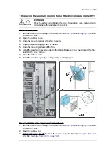
Page 164: ...recautions page 17 before you start the work 2 Open the cabinet door 3 Open the swing out frame or remove the shroud if there is no swing out frame 4 Unplug the power supply wires from the control unit terminal X208 FAN2 5 Lift the fan up 6 Install the new fan in reverse order Make sure that the arrow on the fan points up 7 Close the swing out frame and cabinet door 8 Reset the counter if used in ...

Page 165: ...nplug the power supply cable of the fan 5 Undo the mounting screws of the fan 6 Install the new fan in reverse order to the above Make sure that the arrow in the fan points to the drive module 7 Close the cabinet door 8 Reset the counter in group 5 in the primary control program Fan at the bottom of the circuit board compartment 1 Stop the drive and do the steps in section Electrical safety precau...

Page 166: ...ull the fan cassette out 7 Unplug the power supply cable of the fan 8 Undo the mounting screws of the fan 9 Install the new fan in reverse order to the above Make sure that the arrow in the fan points up 10 Close the swing out frame reinstall the 4 screws and marine supports option C121 and close the cabinet doors 11 Reset the counter if used in group 5 in the primary control program 166 Maintenan...

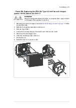
Page 167: ...nt can occur 1 Stop the drive and do the steps in section Electrical safety precautions page 17 before you start the work 2 Slide the front grating upwards and remove it 3 Remove the air filter 4 Loosen the mounting screws of the front mesh Remove the mesh 5 Disconnect the fan supply wires 6 Undo the mounting screws of the fan 7 Pull the fan out 8 Install the new fan in reverse order Maintenance 1...

Page 168: ... 1 Stop the drive and do the steps in section Electrical safety precautions page 17 before you start the work 2 Slide the front gratings upwards and remove them 3 Remove air filters 4 To remove the wire mesh undo the mounting screws 5 Disconnect the fan power supply wires 6 Remove the mounting screws of the fan 7 Remove the fan 8 Install the new fan in reverse order 168 Maintenance ...

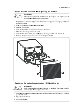
Page 169: ...he four M6 combi screws and remove the mesh 5 Disconnect the fan power supply wires 6 Undo the two M6 combi screws lift the fan assembly upwards and slide it out 7 Remove the mounting screws of the fan and replace the fan Replacing the brake chopper option D150 cubicle fan WARNING Obey the safety instructions of the drive If you ignore them injury or death or damage to the equipment can occur 1 St...

Page 170: ...4 pcs 5 Slide the fan out 6 Install the new fan in reverse order Replacing the sine filter cooling fan For replacing the cooling fans of NSINxxx x sine filters see Sine filters hardware manual 3AXD50000016814 English 170 Maintenance ...

Page 171: ...ns If you ignore them injury or death or damage to the equipment can occur Secure the cabinet to the floor to prevent it from toppling over when you slide out the heavy drive module 1 Stop the drive if running and do the steps in section Electrical safety precautions page 17 before you start the work 2 Open the cabinet door 3 Remove the fuse replacement handle 4 Remove the shroud For drives with o...

Page 172: ...and the control wire terminals on the right side of the cabinet 8 If the swing out frame does not open enough to allow module replacement undo the swing out frame grounding wire and lift the swing out frame off its hinges 9 To remove the mounting plate above the door fan loosen the mounting screws and lift the plate up or remove the shroud and four fixing brackets if there is no mounting plate For...

Page 173: ...10 Unplug the connector and remove the fan or remove the shroud if there is no fan Maintenance 173 ...

Page 174: ...t filter option E205 c three M10 nuts 14 For drives with bottom entry or exit Undo the 7 M6 screws and bend down the left half of the connection terminal subassembly Then bend down the right half of the subassembly so that the power cables do not disturb the module replacement Note If you find it difficult to access the screws of steps 13a or 13c you can disconnect the power cables of step 14 and ...

Page 175: ...per option D150 Undo the two M10 nuts and bend the two power cables down so that they do not disturb the module replacement Bottom exit from module 12 13b 16 13a 14 Bottom exit with E208 or E205 12 16 13a 13c 15 14 Maintenance 175 ...

Page 176: ...plug the connector lift the fan up a bit and remove the fan plate 20 For easier removal of the module undo the four M6 combi screws disconnect the wires of the thermal switch and remove the plastic air guide 21 For easier removal of the module undo the four M6 combi screws and remove the plastic air guide 176 Maintenance ...

Page 177: ...22 Unplug the wires and connectors of X504 mounting plate 23 Undo the four M8 Serpress nuts Maintenance 177 ...

Page 178: ... the end of the sliding bars 26 Slide the drive module towards the end of the sliding bars 27 Secure the drive module with chains from the lifting eyes 28 Lift the module out of the cabinet with a lifting device 29 Loosen the four M5 combi screws and remove X504 mounting plate 30 Remove the four M4 standoffs and place them to a new module 178 Maintenance ...

Page 179: ...31 Place X504 mounting plate to the new module and attach the M5 combi screws 32 Install the new module in reverse order Maintenance 179 ...

Page 180: ...uctions of the drive If you ignore them injury or death or damage to the equipment can occur Handle the drive and LCL filter modules carefully Lift the module only by the lifting lugs Module handling Do not use the module installation ramp with plinth heights which exceeds the maximum allowed height See the technical data Attach the module extraction installation ramp carefully 180 Maintenance ...

Page 181: ...eways tilt of 5 degrees Do not leave the module unattended on a sloping floor 1 2 3 3AUA0000086323 To prevent the drive module from falling attach its top lifting lugs with chains to the cabinet 1 before you push the module into the cabinet and pull it from the cabinet Push the module into the cabinet and pull it from the cabinet carefully preferably with help from another person Keep a constant p...

Page 182: ...frame R11 Replacing the drive module requires preferably two persons 1 Stop the drive if running and do the steps in section Electrical safety precautions page 17 before you start the work 2 Open the cabinet doors 182 Maintenance ...

Page 183: ...ndo the two module attaching screws 3a Undo the M6 screws and remove the three supports 3b Undo the five M6 screws on the left side of the swing out frame 3c D D E E E E E E F F F F F F 3a Combi screw M10 3b M6 3c M6 Maintenance 183 ...

Page 184: ...d bottom 4 pcs 5 Loosen the two M6 screws of the air baffle and push it to the left Not for drives with option C128 6 Remove the air baffle 7 Remove the air baffle Not for drives with option C121 8 Remove the air baffle 8a in IP22 IP42 drives 8b in IP54 drives 184 Maintenance ...

Page 185: ...inal X2 INU STO connector and the fiber optic cables from the V8 V13 V2 and V7 connectors E D The connections between the line side converter control unit and drive are shown below The drive control unit remains in its place when you remove the drive module Maintenance 185 ...

Page 186: ... 9 10 Loosen the M4 screws lift the plastic shroud of the DC busbars up and remove it 11 Disconnect the input power cabling busbars from the drive module busbar terminals For drives with option D150 disconnect the DC busbars also 186 Maintenance ...

Page 187: ...12 Disconnect the output power cabling and PE busbars from the drive module busbar terminals 0 1āP OEIāIW 0 1āP OEIāIW Hex screw Hex screw Maintenance 187 ...

Page 188: ... Remove the attaching bolt 13d Remove the shroud 13e Remove the bolts 13f Disconnect the power wire of the LCL filter fan from connector FAN3 LCL D G H H E F I 14 To open the support legs 90 degrees press each leg a little down and turn it aside 15 To remove the lower support bracket of the drive module undo the two screws 188 Maintenance ...

Page 189: ...onstruction option C121 Remove the bolts that attach the drive module to the cabinet frame at the lower part 18 To remove the shroud on the charging circuit switch contactor undo the two mounting screws 19 Unplug the connector and auxiliary contact wires of the charging circuit switch contactor 20 Undo the two bolts that attach drive module to the LCL filter module Maintenance 189 ...

Page 190: ...e cabinet frame Combi screw M4 Combi screw M8 Combi screw M10 22 Attach the lifting lugs of the module to be removed to the cabinet lifting lug with chains 23 Pull the module carefully out of the cabinet preferably with help from another person 190 Maintenance ...

Page 191: ...1 To open the support legs 90 degrees press each leg a little down and turning it aside 2 To remove the lower support bracket of the LCL filter module undo the two screws 3 Adjust the extraction ramp to the correct height and attach it to the cabinet base with the two mounting screws of the lower support bracket that was removed 4 Undo the two lower screws that attach the LCL filter module to the ...

Page 192: ...o the 5 bolts that attach LCL filter module from back and from the right to the cabinet frame 2 3 7 Attach the lifting lugs of the module to be removed to the cabinet lifting lug with chains 192 Maintenance ...

Page 193: ...ontact ABB Reforming the capacitors The capacitors must be reformed if the drive has not been powered either in storage or unused for a year or more The manufacturing date is on the type designation label For information on reforming the capacitors see Capacitor reforming instructions 3BFE64059629 English in the ABB Library https library abb com en Fuses Replacing fuses frame R8 WARNING Obey the s...

Page 194: ... replacement handle 4 Remove the shroud 5 Remove the top mounting plate 6 Pull out the fuses with the fuse handle and replace them with the new fuses 7 Reinstall the mounting plate shroud and fuse handle 194 Maintenance ...

Page 195: ...rame and open the swing out frame or remove the shroud if there is no swing out frame Remove the plate under the swing out frame if present or remove the shroud 4 Remove the plastic shroud in front of the fuses Note You can access the screws on the left side of the fuse shroud easier if you open the swing out frame slightly and use the gap between the swing out frame and cabinet frame to access th...

Page 196: ... 196 Maintenance ...

Page 197: ...drive if running and do the steps in section Electrical safety precautions page 17 before you start the work 2 Open the door of the brake chopper cubicle 3 Remove the upper shroud undo 10 pcs of M6 combi screws 4 Remove the M10 bolts and nuts that fasten the fuses to fuse bases Remove the fuses 5 Install new fuses to the fuse bases Make sure to keep the washers in original order Tighten the screws...

Page 198: ...unit 3 To see the battery remove the XD2D terminal block 4 Carefully lift the edge of the control unit cover on the side with the I O terminal blocks 5 Carefully pull the battery out of the battery holder 6 Carefully put a new CR2032 battery into the battery holder 7 Close the control unit cover 8 Tighten the M4 8 T20 screws 9 Install the XD2D terminal block 2 2 8 8 4 5 6 7 9 3 Memory unit When a ...

Page 199: ...e drive This can take several minutes Replacing the memory unit of the motor side converter control unit frame R8 WARNING Obey the safety instructions of the drive If you ignore them injury or death or damage to the equipment can occur If you are not a qualified electrical professional do not do installation or maintenance work Maintenance 199 ...

Page 200: ...cabinet door and swing out frame or remove the shroud if there is no swing out frame The control unit is located behind swing out frame or shroud 2 3 Undo the memory unit mounting screw and take the memory unit out Replace the unit in reverse order Note There is a spare screw next to the memory unit slot 200 Maintenance ...

Page 201: ...e 17 before you start the work 2 Open the cabinet doors The control unit is located on the module side swing out frame For the location see also section Cabinet layout page 36 2 3 Remove the mounting screw 4 Pull the memory unit out 5 Install the new memory unit in reverse order Note There is a spare screw next to the memory unit slot X205 Maintenance 201 ...

Page 202: ...Stop the drive and do the steps in section Electrical safety precautions page 17 before you start the work To remove the marine supports in drives with option C121 see Replacing the drive and LCL filter modules frame R11 To open the module section swing out frame undo the M10 bolts from top and bottom 4 pcs See Replacing the drive and LCL filter modules frame R11 2 Remove the cover on the memory u...

Page 203: ...rine specific data and reference to valid marine type approvals Ratings The nominal ratings for the drives with 50 Hz and 60 Hz supply are given below The symbols are described in section Definitions page 205 IEC ratings Output ratings Nominal ratings Input current Frame size Drive type ACS880 37 Heavy duty use Light overload use PHd IHd PLd ILd SN PN Imax I2 I1 kW A kW A kVA kW A A A UN 400 V 45 ...

Page 204: ... 361 257 R11 0361A 5 200 361 250 393 359 250 542 414 321 R11 0414A 5 250 414 315 450 398 315 560 460 404 R11 0460A 5 315 460 355 492 436 355 560 503 455 R11 0503A 5 UN 690 V 132 142 160 165 208 160 274 174 149 R11 0174A 7 160 174 200 200 251 200 384 210 186 R11 0210A 7 200 210 250 257 324 250 411 271 232 R11 0271A 7 250 271 315 320 394 315 480 330 293 R11 0330A 7 315 330 355 360 442 355 520 370 33...

Page 205: ...ng as allowed by drive tempera ture Imax Typical motor power in no overload use PN Apparent power in no overload use SN Continuous rms output current allowing 10 overload for 1 minute every 5 minutes ILd 1 No overload Typical motor power in light overload use PLd Continuous rms output current allowing 50 overload for 1 minute every 5 minutes IHd Typical motor power in heavy duty use PHd Note The r...

Page 206: ...3281 6562 ft above sea level the output current derating is 1 percentage point for every added 100 m 328 ft For example the derating factor for 1500 m 4921 ft is 0 95 For altitudes above 2000 m 6562 ft contact ABB If surrounding air temperature is below 40 C 104 F the derating can be reduced by 1 5 percentage points for every 1 C 1 8 F reduction in temperature A few altitude derating curves are sh...

Page 207: ... current derating Ex motor sine filter low noise The ratings in these cases are given in the table below drive is used with an ABB motor for explosive atmospheres Ex and EX motor in parameter 95 15 Special HW settings is enabled sine filter option E206 is selected and ABB sine filter in parameter 95 15 Special HW settings is enabled Low noise optimization is selected in parameter 97 09 Switching f...

Page 208: ...75 148 75 156 75 148 75 156 0156A 5 156 171 180 90 171 90 180 90 171 90 180 0180A 5 210 216 160 229 216 222 160 234 228 235 160 247 0260A 5 227 264 250 hp 266 234 272 250 hp 272 247 287 250 hp 287 0302A 5 UN 480 V 227 300 200 318 234 309 200 325 247 326 200 343 0361A 5 315 343 250 365 325 354 250 373 343 373 250 393 0414A 5 362 393 250 406 373 405 315 414 393 428 315 437 0460A 5 402 430 315 443 41...

Page 209: ...frequency no derating Heavy duty use Light duty use Nominal use Heavy duty use Light duty use Nominal use IHd ILd PN IN IHd ILd PN IN A A kW A A A kW A UN 400 V 87 100 105 87 100 55 105 0105A 3 105 138 145 105 138 75 145 0145A 3 122 148 156 145 161 90 169 0169A 3 155 180 192 169 196 110 206 0206A 3 203 229 132 240 246 278 160 293 0293A 3 241 284 200 297 293 345 200 363 0363A 3 299 346 250 362 363 ...

Page 210: ...0 355 370 0370A 7 213 241 250 247 370 420 400 430 0430A 7 Output frequency f Maximum output frequency with High speed mode fmax Nominal voltage of the drive UN Continuous rms output current No overload capability at 40 C 104 F IN Typical motor power in no overload use PN Continuous rms output current allowing 10 overload for 1 minute every 5 minutes ILd Typical motor power for light overload use P...

Page 211: ...0 505 0585A 3 3 170M6414 Bussmann 690 945000 1000 569 0650A 3 UN 500 V 1 170M3814D Bussmann 690 8250 160 71 0101A 5 1 170M3816D Bussmann 690 31000 250 96 0124A 5 1 170M3816D Bussmann 690 31000 250 115 0156A 5 1 170M3817D Bussmann 690 52000 315 141 0180A 5 2 170M5408 Bussmann 690 74000 400 205 0260A 5 3 170M6410 Bussmann 690 210000 630 257 0361A 5 3 170M6411 Bussmann 690 300000 700 321 0414A 5 3 17...

Page 212: ...61A 5 2 SC32AR69V700TF Mersen 690 442000 700 321 0414A 5 2 SC32AR69V700TF Mersen 690 442000 700 404 0460A 5 2 SC32AR69V800TF Mersen 690 660000 800 455 0503A 5 UN 690 V 149 0174A 7 186 0210A 7 2 SC32AR69V500TF Mersen 690 160000 500 232 0271A 7 2 SC32AR69V630TF Mersen 690 315000 630 293 0330A 7 2 SC32AR69V630TF Mersen 690 315000 630 330 0370A 7 2 SC32AR69V700TF Mersen 690 442000 700 375 0430A 7 Note...

Page 213: ...J 300 Bussmann 600 300 176 0206A 3 2 170M5410 Bussmann 690 500 257 0293A 3 3 170M6410 Bussmann 690 630 321 0363A 3 3 170M6411 Bussmann 690 700 401 0442A 3 3 170M6412 Bussmann 690 800 401 0505A 3 3 170M6414 Bussmann 690 1000 505 0585A 3 3 170M6414 Bussmann 690 1000 569 0650A 3 UN 480 V Class J DFJ 250 Bussmann 600 250 74 0101A 5 Class J DFJ 250 Bussmann 600 250 100 0124A 5 Class J DFJ 250 Bussmann ...

Page 214: ...mm 19 68 in Extra width with EMC filter option E202 200 mm 7 87 in for frame R8 and 400 mm 15 75 in for frame R11 For drives with marine attaching bars option C121 Depth is 757 mm 29 80 in 3 Dimensions and weights of sine filter cabinet option E206 Weight Depth Width Height Frame size IP54 IP22 42 lb kg in mm in mm in mm in mm UN 400 V 728 330 25 43 646 23 62 600 91 14 2315 84 45 2145 0105A 3 728 ...

Page 215: ...145 0460A 5 1852 840 25 43 646 39 37 1000 91 14 2315 84 45 2145 0503A 5 UN 690 V 904 410 25 43 646 23 62 600 91 14 2315 84 45 2145 0174A 7 904 410 25 43 646 23 62 600 91 14 2315 84 45 2145 0210A 7 904 410 25 43 646 23 62 600 91 14 2315 84 45 2145 0271A 7 750 340 25 43 646 15 75 400 91 14 2315 84 45 2145 0330A 7 750 340 25 43 646 15 75 400 91 14 2315 84 45 2145 0370A 7 750 340 25 43 646 15 75 400 9...

Page 216: ... 77 3 35 13 16 1177 2000 1279 2100 0585A 3 80 77 3 73 14 78 1177 2000 1279 2100 0650A 3 UN 500 V 70 70 0 63 2 32 412 700 0101A 5 70 70 0 63 3 14 412 700 0124A 5 70 70 0 55 3 54 412 700 0156A 5 70 70 0 55 4 27 474 805 0180A 5 77 77 0 9 6 86 1279 2100 0260A 5 77 77 1 57 1279 2100 0302A 5 77 77 1 57 8 50 1279 2100 0361A 5 77 77 1 57 10 51 1279 2100 0414A 5 80 77 3 16 13 15 1177 2000 1279 2100 0460A 5...

Page 217: ... 0505A 3 2000 1177 3 35 527 NSIN0900 6 1 0585A 3 2000 1177 3 73 585 NSIN0900 6 1 0650A 3 UN 500 V 0 63 101 B84143V0130S230 1 0101A 5 0 63 124 B84143V0130S230 1 0124A 5 0 55 156 B84143V0162S229 1 0156A 5 0 55 180 B84143V0162S229 1 0180A 5 0 90 234 B84143V0230S229 1 0260A 5 1 57 272 B84143V0390S229 1 0302A 5 1 57 325 B84143V0390S229 1 0361A 5 1 557 373 B84143V0390S229 1 0414A 5 2000 1177 3 16 414 NS...

Page 218: ...0 2 3 150 R11 0414A 5 2 400 MCM or 3 4 0 3 3 120 2 3 185 R11 0460A 5 2 500 MCM or 3 250 MCM 3 3 150 3 3 95 R11 0503A 5 UN 690 V 4 0 2 3 70 3 120 R11 0174A 7 300 MCM 2 3 95 3 185 R11 0210A 7 400 MCM 2 3 120 3 240 R11 0271A 7 2 250 MCM or 3 2 0 2 3 150 2 3 95 R11 0330A 7 2 300 MCM or 3 3 0 2 3 150 2 3 120 R11 0370A 7 3 120 2 350 MCM or 3 4 0 3 3 120 2 3 185 R11 0430A 7 The cable sizing is based on m...

Page 219: ...5 Strength class 8 8 10 N m 7 4 lbf ft M6 Strength class 8 8 24 N m 17 7 lbf ft M8 Insulation supports Note Max torque Size Strength class 8 8 5 N m 44 lbf in M6 Strength class 8 8 9 N m 6 6 lbf ft M8 Strength class 8 8 18 N m 13 3 lbf ft M10 Strength class 8 8 31 N m 23 lbf ft M12 Cable lugs Note Max torque Size Strength class 8 8 15 N m 11 lbf ft M8 Strength class 8 8 32 N m 23 5 lbf ft M10 Stre...

Page 220: ...ted in the type designation label as typical input voltage level 3 400 V AC Voltage U1 ACS880 37 xxxxx 5 drives 380 500 VAC 3 phase 10 15 This is indicated in the type designation label as typical input voltage levels 3 400 480 500 V AC ACS880 37 xxxxx 7 drives 525 690 VAC 3 phase 10 15 This is indicated in the type designation label as typical input voltage levels 3 525 600 690 V AC TN grounded a...

Page 221: ...e voltage distortion This value is defined as the ratio in of the harmonic voltage to the fundamental non harmonic voltage THDv Indicates the total harmonic current distortion of the wave form This value is defined as the ratio in of the harmonic current to the fundamental non harmonic current measured at a load point at the particular moment when the measurement is taken THDv 40 2 n 2 U U1 100 TH...

Page 222: ...it connection data See chapter Control units of the drive page 133 Efficiency 97 at nominal power level Protection classes IP22 Degrees of protection IEC EN 60529 IP42 option B054 IP54 option B055 III Overvoltage category IEC EN 60664 1 I Protective class IEC EN 61800 5 1 Ambient conditions Environmental limits for the drive are given below The drive is to be used in a heated indoor controlled env...

Page 223: ...EN 60721 3 1 1997 IEC EN 60721 3 3 2002 Vibration 2 9 Hz max 3 5 mm amplitude 10 57 Hz max 0 075 mm amplitude 10 57 Hz max 0 075 mm amplitude IEC EN 61800 5 1 IEC 60068 2 6 2007 EN 60068 2 6 2008 Envir onmental testing Part 2 Tests Test Fc Vibration sinusoidal 9 200 Hz 10 m s2 32 8 ft s2 57 150 Hz 1 g 57 150 Hz 1 g Units with marine construc tion option C121 Max 1 mm 0 04 in 5 13 2 Hz max 0 7 g 13...

Page 224: ...cted conditions Seaworthy package timber plywood VCI sheet film PE thickness 0 10 mm VCI stretch film PE thickness 0 04 mm VCI emitter bags PP tape PET strap sheet metal steel for sea transport with or without containerization for long storage periods in environments where roofed and humidity controlled storage cannot be arranged Cabinets are fastened to the pallet with screws and braced from the ...

Page 225: ...tage switchgear and control gear assemblies Part 1 General rules IEC EN 61439 1 2011 Enclosures for Electrical Equipment Non Environmental Considerations 13th UL 50 2015 edition UL Standard for Safety Power Conversion UL 508A 2016 UL Standard for Industrial Control Panels second edition UL 508A 2013 EMC performance Adjustible speed electrical power drive systems Part 3 EMC requirements and specifi...

Page 226: ... attached to the drive to verify that the drive complies with the provisions of the European Low Voltage and EMC Directives The CE marking also verifies that the drive in regard to its safety functions such as Safe torque off conforms with the Machinery Directive as a safety component Compliance with the European Low Voltage Directive The compliance with the European Low Voltage Directive has been...

Page 227: ...or use in complex systems in the second environment Category C2 The drive complies with the standard with the following provisions 1 The drive is equipped with EMC filter option E202 2 The motor and control cables are selected as specified in the hardware manual 3 The drive is installed according to the instructions given in the hardware manual 4 Maximum motor cable length is 100 meters 328 ft WAR...

Page 228: ...rk 1 Supply transformer 7 Neighboring network 2 Static screen 8 Point of measurement 3 Drive 9 Low voltage 4 Equipment victim 5 2 An EMC plan for preventing disturbances is drawn up for the installation A template is available in Technical guide No 3 EMC compliant installation and configuration for a power drive system 3AFE61348280 English 3 The motor and control cables are selected and routed acc...

Page 229: ...elsewhere in this chapter The ampere rating is based on tests done according to the appropriate UL standard The cables located within the motor circuit must be rated for at least 75 C 167 F in UL compliant installations The input cable must be protected with fuses The fuses must provide branch circuit protection in accordance with the national regulations National Electrical Code NEC or Canadian E...

Page 230: ...usly ensure a secure connection between the product and Customer network or any other network as the case may be Customer shall establish and maintain any appropriate measures such as but not limited to the installation of firewalls application of authentication measures encryption of data installation of anti virus programs etc to protect the product the network its system and the interface again...

Page 231: ...Dimension drawings Contents of this chapter This chapter contains example dimension drawings 13 Dimension drawings 231 ...

Page 232: ...R8 IP22 UL Type 1 and option B054 IP42 UL Type 1 Filtered 232 Dimension drawings ...

Page 233: ...R8 IP54 UL Type 12 option B055 option C129 Dimension drawings 233 ...

Page 234: ...R8 IP22 UL Type 1 and IP42 UL Type 1 Filtered option B054 options D150 D151 234 Dimension drawings ...

Page 235: ...R8 IP22 UL Type 1 and IP42 UL Type 1 Filtered option B054 option E206 Dimension drawings 235 ...

Page 236: ...R8 IP22 UL Type 1 option E202 236 Dimension drawings ...

Page 237: ...R11 IP22 UL Type 1 and IP42 UL Type 1 Filtered option B054 Dimension drawings 237 ...

Page 238: ...R11 IP54 UL Type 12 option B055 238 Dimension drawings ...

Page 239: ...R11 IP22 UL Type 1 and IP42 UL Type 1 Filtered option B054 options C129 H350 H352 Dimension drawings 239 ...

Page 240: ...R11 IP54 UL Type 12 option B055 option C128 240 Dimension drawings ...

Page 241: ...R11 IP54 UL Type 12 option B055 option C129 Dimension drawings 241 ...

Page 242: ...R11 IP54 UL Type 12 option B055 options C129 H350 H352 242 Dimension drawings ...

Page 243: ...R11 IP22 UL Type 1 and IP42 UL Type 1 Filtered option B054 option D150 Dimension drawings 243 ...

Page 244: ...R11 IP22 UL Type 1 and IP42 UL Type 1 Filtered option B054 options D150 D151 244 Dimension drawings ...

Page 245: ...R11 IP22 UL Type 1 and IP42 UL Type 1 Filtered option B054 option E206 Dimension drawings 245 ...

Page 246: ...R11 IP22 UL Type 1 option E202 246 Dimension drawings ...

Page 247: ...Location and size of power cable connection terminals R8 input and motor cable terminal dimensions bottom entry and exit Dimension drawings 247 ...

Page 248: ... R8 input and motor cable terminal dimensions top entry and exit options H351 and H353 248 Dimension drawings ...

Page 249: ... R8 input and motor cable terminals R11 input and motor cable terminal dimensions bottom entry and exit Dimension drawings 249 ...

Page 250: ... R11 input and motor cable terminal dimensions top entry and exit options H351 and H353 R11 input cable terminals 250 Dimension drawings ...

Page 251: ... R11 motor cable terminals Terminals for connecting external resistors Sine filter E206 cubicle 400 mm motor cable terminals Dimension drawings 251 ...

Page 252: ... Sine filter E206 cubicle 600 mm motor cable terminals Sine filter E206 cubicle 1000 mm motor cable terminals 252 Dimension drawings ...

Page 253: ...intenance operations like cleaning or work on non electrical parts of the machinery without switching off the power supply to the drive When activated the Safe torque off function disables the control voltage of the power semiconductors of the drive output stage A see the diagrams below thus preventing the drive from generating the torque required to rotate the motor If the motor is running when S...

Page 254: ...s for electrical electronic program mable electronic safety related systems IEC 61508 2 2010 Functional safety Safety instrumented systems for the process industry sector IEC 61511 1 2016 Adjustable speed electrical power drive systems Part 5 2 Safety require ments Functional IEC 61800 5 2 2016 EN 61800 5 2 2007 Safety of machinery Functional safety of safety related electrical elec tronic and pro...

Page 255: ...cable is recommended Maximum cable lengths 300 m 1000 ft between activation switch K and drive control unit 60 m 200 ft between multiple drives or inverter units 60 m 200 ft between external power supply and first control unit Note A short circuit in the wiring between the switch and an STO terminal causes a dangerous fault Therefore it is recommended to use a safety relay including wiring diagnos...

Page 256: ... 24 V OUT SGND IN2 K IN1 1 2 Note Both STO inputs IN1 IN2 must be connected to the activation switch Otherwise no SIL PL classification is given Pay special attention to avoiding any potential failure modes for the wiring For example use shielded cable For measures for fault exclusion of wiring see eg EN ISO 13849 2 2012 table D 4 Drive 1 Control unit 2 Activation switch K OUT1 with ZCU 12 control...

Page 257: ...4 V OUT SGND IN1 IN2 OUT SGND IN1 IN2 OUT SGND IN1 IN2 K XSTO XSTO XSTO 1 1 1 2 2 2 Drive Inverter unit 1 Control unit 2 Activation switch K Terminal designation may vary depending on drive inverter unit type The Safe torque off function 257 ...

Page 258: ...IN2 OUT SGND IN1 IN2 OUT SGND IN1 IN2 24 V 24 V DC K XSTO XSTO XSTO 1 2 1 2 1 2 Drive Inverter unit 1 Control unit 2 Activation switch K Terminal designation may vary depending on drive inverter unit type 258 The Safe torque off function ...

Page 259: ... this occurs Note This parameter does not affect the operation of the STO function itself The STO function will operate regardless of the setting of this parameter a running drive will stop upon removal of one or both STO signals and will not start until both STO signals are restored and all faults reset Note The loss of only one STO signal always generates a fault as it is interpreted as a malfun...

Page 260: ... test procedure After wiring the Safe torque off function validate its operation as follows Note If the drive is equipped with safety option L536 L537 Q950 Q951 Q952 Q957 Q963 Q964 Q978 or Q979 do the procedure shown in the documentation of the option Action WARNING Obey the safety instructions If you ignore them injury or death or damage to the equipment can occur Make sure that the drive can be ...

Page 261: ...o IN1 If the motor was running it should coast to a stop The drive generates a FA81 Safe Torque Off 1 loss fault indication see the firmware manual Give a start command to verify that the STO function blocks the drive s operation The motor should not start Close the STO circuit Reset any active faults Restart the drive and check that the motor runs normally Open the 2nd channel of the STO circuit ...

Page 262: ...ent magnet or synchronous reluctance SynRM motors only In case of a multiple IGBT power semiconductor failure the drive can produce an alignment torque which maximally rotates the motor shaft by 180 p degrees with permanent magnet motors or 180 2p degrees with synchronous reluctance SynRM motors regardless of the activation of the Safe torque off function p denotes the number of pole pairs Notes I...

Page 263: ...tegrity requirement for the safety function is SIL 2 HFT 1 or PL d cat 3 the proof test for the function must be performed at least every 12 months The STO function of the drive does not contain any electromechanical components In addition to proof testing it is a good practice to check the operation of the function when other maintenance procedures are carried out on the machinery Include the Saf...

Page 264: ...function is performed and the drive trips on an STO hardware failure fault An attempt to use the STO in a non redundant manner for example activating only one channel will trigger the same reaction See the firmware manual of the drive control program for the indications generated by the drive and for details on directing fault and warning indications to an output on the control unit for external d...

Page 265: ...ure The STO does not activate when requested A fault exclusion on the failure mode short circuit on printed circuit board has been made EN 13849 2 table D 5 The analysis is based on an assumption that one failure occurs at one time No accumulated failures have been analyzed STO response times STO reaction time shortest detectable break 1 ms STO response time Frame R8 2 ms typical 5 ms maximum Fram...

Page 266: ...ability IEC 61508 SC Safe failure fraction IEC 61508 SFF Safety integrity level 1 3 IEC 61508 SIL Maximum SIL level 1 3 that can be claimed for a safety function or subsystem IEC EN 62061 SILCL Safe torque off IEC EN 61800 5 2 STO Proof test interval T1 is a parameter used to define the probabilistic failure rate PFH or PFD for the safety function or subsystem Per forming a proof test at a maximum...

Page 267: ... Declaration of conformity The Safe torque off function 267 ...

Page 268: ...268 The Safe torque off function ...

Page 269: ... energy generated by a decelerating motor The chopper connects the brake resistor to the intermediate DC circuit whenever the voltage in the circuit exceeds the limit defined by the control program Energy consumption by the resistor losses lowers the voltage until the resistor can be disconnected Planning the braking system Selecting the default brake circuit components ABB chopper and ABB resisto...

Page 270: ... energy transferred during any 600 second period must be smaller than or equal to the energy that is transferred during the reference braking cycle of 40 seconds every 600 seconds where Number of the braking pulses during the 600 second period n Braking power of the custom duty cycle in kW Pbr Braking time within the custom duty cycle in seconds tbr Maximum braking power allowed for 40 seconds eve...

Page 271: ...oltage is 525 to 690 V AC UDC Resistance of the custom resistor R 3 make sure that the resistor can dissipate the energy transferred to it during the braking Braking energy is not greater than the resistor heat dissipation capacity Er during the period specified See the custom resistor specification The resistor is installed in a properly ventilated and cooled space Otherwise the resistor cannot m...

Page 272: ...y 600 seconds where Number of the braking pulses during the 600 second period n Braking power of the custom duty cycle in kW Pbr Braking time within the custom duty cycle in seconds tbr Maximum braking power allowed for 60 seconds every 600 seconds See the value in the ratings of the factory installed brake choppers and custom resistors Pbr max Example 1 The duration of a braking cycle is three mi...

Page 273: ... suppresses the radiated emissions Install the cables away from other cable routes Avoid long parallel runs with other cables The minimum parallel cabling separation distance is 0 3 meters 1 ft Cross the other cables at 90 degree angles Keep the cable as short as possible in order to minimize the radiated emissions and stress on chopper IGBTs The longer the cable the greater the radiated emissions...

Page 274: ...the cables are dimensioned according to the nominal current of the drive The drive control program includes a resistor overload protection function which can be tuned by the user See the firmware manual Thermal protection of the resistors The standard resistors available as option D151 are equipped with a thermal switch The switches of the resistors are wired in series and connected to the Enable ...

Page 275: ...them injury or death or damage to the equipment can occur If you are not a qualified electrical professional do not do installation or maintenance work Do not make any voltage tolerance or insulation resistance tests on the brake chopper modules Every brake chopper module has been tested for insulation between the main circuit and the chassis at the factory Measure the insulation of the brake resi...

Page 276: ...rmal switch of the brake resistor to the enable input X1 on the brake chopper control board Use cable specified under Thermal protection of the resistors page 274 If there are multiple thermal switches connect them in series WARNING The ENABLE input terminal block of the brake chopper is at intermediate circuit potential when the line side converter of the drive is running This voltage is extremel...

Page 277: ... For calculating the maximum allowed braking power with a custom duty cycle see the braking system planning instructions for factory installed brake chopper and ABB resistor Duty cycle 1 5 min Duty cycle 10 60 s Imax A Pbr cont kW Pbr max kW 40 s R ohm Resistors Brake chopper UN Irms A Pbr kW Irms A Pbr kW 195 130 336 224 345 42 230 1 7 2 x SAFUR210F575 NBRA 658 400 V 250 167 430 287 532 60 355 1 ...

Page 278: ...43 136 571 109 403 NBRA 659 1096 1120 267 298 361 404 2 72 107 414 119 403 NBRA 669 690 V Nominal voltage UN Maximum braking power allowed for 40 seconds every 600 seconds Pbr max Maximum continuous braking power Pbr cont Maximum current Imax ms current Irms Recommended resistance R Braking power for the specified duty cycle Pbr DC voltage at which chopper starts conducting Ubr on DC voltage at wh...

Page 279: ...A 5 170M8635 Bussmann 630 0302A 5 170M8635 Bussmann 630 0361A 5 170M8635 Bussmann 630 0414A 5 170M8635 Bussmann 630 0460A 5 170M8635 Bussmann 630 0503A 5 UN 690 V 170M5142 Bussmann 400 0174A 7 170M5142 Bussmann 400 0210A 7 170M5142 Bussmann 400 0271A 7 170M5142 Bussmann 400 0330A 7 170M5142 Bussmann 400 0370A 7 170M5142 Bussmann 400 0430A 7 Terminals and cable entry data of factory installed chopp...

Page 280: ...280 ...

Page 281: ... by navigating to www abb com searchchannels Product training For information on ABB product training navigate to new abb com service training Providing feedback on ABB manuals Your comments on our manuals are welcome Navigate to new abb com drives manuals feedback form Document library on the Internet You can find manuals and other product documents in PDF format on the Internet at www abb com dr...

Page 282: ...www abb com drives 3AXD50000035159G Copyright 2020 ABB All rights reserved Specifications subject to change without notice 3AXD50000035159 Rev G EN EFFECTIVE 2020 03 25 ...

Reviews: