■
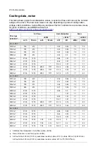
IEC
Grounding terminals
Terminals L1, L2, L3, U2, V2, W2, UDC+/R+, UDC-
and R-
Number of holes
in the entry
plate for the
power cables.
Hole diameter
60 mm.
Frame
size
Tightening
torque
Bolt
size
Tightening
torque
Bolt size
Max. phase con-
ductor size
N·m
mm
2
50…75 N·m
M12
20…40 N·m
M10
185
6…12
R8
50…75 N·m
M12
50…75 N·m
M12
3×240 or 4×185
12
R11
■
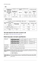
North America
Grounding terminals
Terminals L1, L2, L3, U2, V2, W2, UDC+/R+, UDC- and R-
Frame
size
Tightening torque
Bolt
size
Tightening torque
Busbar bolt size –
Hole spacing
Max. phase conduct-
or size
bf·ft
bf·ft
AWG/kcmil
37…55
M10
(3/8")
15…30
M12 7/16") × 1 – 1.75”
350 MCM...1×500
MCM or 4×350 MCM
R8
37…55
M10
(3/8")
37…55
M12 (7/16") × 3 –
1.75”
1×500 MCM or 4×350
MCM
R11
Terminal data for the drive control unit
See chapter
Control units of the drive (page 133)
.
Electrical power network specification
ACS880-37-xxxxx-3 drives: 380…415 VAC 3-phase +10%…-15%. This is indicated in
the type designation label as typical input voltage level. 3 ~ 400 V AC.
Voltage (U
1
)
ACS880-37-xxxxx-5 drives: 380…500 VAC 3-phase +10%…-15%. This is indicated in
the type designation label as typical input voltage levels. 3 ~ 400/480/500 V AC.
ACS880-37-xxxxx-7 drives: 525…690 VAC 3-phase +10%…-15%. This is indicated in
the type designation label as typical input voltage levels. 3 ~ 525/600/690 V AC.
TN (grounded) and IT (ungrounded) systems
Network type
50/60 Hz, Variation ± 5% of nominal frequency
Frequency (f
1
)
Max. ± 3% of nominal phase-to-phase voltage
Imbalance
Maximum allowable prospective short-circuit current is 65 kA when the input cable is
protected with gG type fuses (IEC 60269) having maximum operating time of 0.1 seconds
and maximum current rating as follows:
Short-circuit with-
stand strength (IEC
61439-1)
• 400 A for frame R8
• 1250 A for frame R11.
The drive is suitable for use on a circuit capable of delivering not more than 100,000
rms symmetrical amperes at 600 V maximum when the input cable is protected with
class T fuses.
Short-circuit cur-
rent protection (UL
508C)
220 Technical data
Summary of Contents for ACS880-37
Page 1: ... ABB INDUSTRIAL DRIVES ACS880 37 drives 45 400 kW 60 450 hp Hardware manual ...
Page 2: ......
Page 4: ......
Page 26: ...26 ...
Page 83: ...Mechanical installation 83 10 ...
Page 84: ...84 ...
Page 126: ... B055 a X504 126 Electrical installation ...
Page 144: ...144 ...
Page 150: ...150 ...
Page 152: ...152 ...
Page 160: ... 160 Maintenance ...
Page 196: ... 196 Maintenance ...
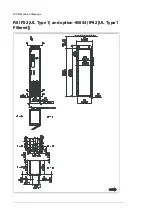
Page 232: ...R8 IP22 UL Type 1 and option B054 IP42 UL Type 1 Filtered 232 Dimension drawings ...
Page 233: ...R8 IP54 UL Type 12 option B055 option C129 Dimension drawings 233 ...
Page 235: ...R8 IP22 UL Type 1 and IP42 UL Type 1 Filtered option B054 option E206 Dimension drawings 235 ...
Page 236: ...R8 IP22 UL Type 1 option E202 236 Dimension drawings ...
Page 237: ...R11 IP22 UL Type 1 and IP42 UL Type 1 Filtered option B054 Dimension drawings 237 ...
Page 238: ...R11 IP54 UL Type 12 option B055 238 Dimension drawings ...
Page 240: ...R11 IP54 UL Type 12 option B055 option C128 240 Dimension drawings ...
Page 241: ...R11 IP54 UL Type 12 option B055 option C129 Dimension drawings 241 ...
Page 242: ...R11 IP54 UL Type 12 option B055 options C129 H350 H352 242 Dimension drawings ...
Page 243: ...R11 IP22 UL Type 1 and IP42 UL Type 1 Filtered option B054 option D150 Dimension drawings 243 ...
Page 245: ...R11 IP22 UL Type 1 and IP42 UL Type 1 Filtered option B054 option E206 Dimension drawings 245 ...
Page 246: ...R11 IP22 UL Type 1 option E202 246 Dimension drawings ...
Page 267: ... Declaration of conformity The Safe torque off function 267 ...
Page 268: ...268 The Safe torque off function ...
Page 280: ...280 ...

