The drive is suitable for use on a circuit capable of delivering not more than 100,000
rms symmetrical amperes at 600 V maximum when the input cable is protected with T
class fuses.
Short-circuit cur-
rent protection
(CSA C22.2 No. 14-
13)
cos phi
1
= 1, cos phi (total) = 0.99
Power factor
Harmonics are below the limits defined in IEEE 519-2014, and G5/4. The drive complies
with IEC 61000-3-2, IEC 61000-3-4 and IEC 61000-3-12.
Harmonic distor-
tion
The table below shows typical values of the drive for short-circuit ratio (
I
sc
/
I
1
) of 20 to
100. The values will be met if the supply network voltage is not distorted by other loads
and when the drive operates at nominal load.
THDv (%)
THDi (%)
Nominal bus voltage V at PCC
< 3**
3*
V ≤ 690 V
Indicates the total magnitude of the voltage distortion. This value is defined
as the ratio (in %) of the harmonic voltage to the fundamental (non-harmonic)
voltage:
THDv
Indicates the total harmonic current distortion of the wave form. This value is
defined as the ratio (in %) of the harmonic current to the fundamental (non-
harmonic) current measured at a load point at the particular moment when the
measurement is taken:
THDv =
40
2
n
2
∑
U
U
1
•
100%
THDi
Point on a public power supply system, electrically nearest to a particular load,
at which other loads are, or could be, connected. The PCC is a point located
upstream of the considered installation.
THDi =
40
2
n
2
∑
I
I
1
•
100%
PCC
Short-circuit ratio
I
sc
/
I
1
Maximum short-circuit current at PCC
I
sc
Continuous rms input current of the drive
I
1
Amplitude of the current harmonic n
I
n
Supply voltage
U
1
Amplitude of the voltage harmonic n
U
n
* The short-circuit ratio can influence the THDi value
** Other loads can influence the THDv value
Technical data 221
Summary of Contents for ACS880-37
Page 1: ... ABB INDUSTRIAL DRIVES ACS880 37 drives 45 400 kW 60 450 hp Hardware manual ...
Page 2: ......
Page 4: ......
Page 26: ...26 ...
Page 83: ...Mechanical installation 83 10 ...
Page 84: ...84 ...
Page 126: ... B055 a X504 126 Electrical installation ...
Page 144: ...144 ...
Page 150: ...150 ...
Page 152: ...152 ...
Page 160: ... 160 Maintenance ...
Page 196: ... 196 Maintenance ...
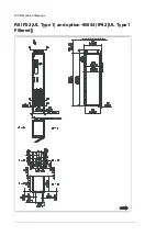
Page 232: ...R8 IP22 UL Type 1 and option B054 IP42 UL Type 1 Filtered 232 Dimension drawings ...
Page 233: ...R8 IP54 UL Type 12 option B055 option C129 Dimension drawings 233 ...
Page 235: ...R8 IP22 UL Type 1 and IP42 UL Type 1 Filtered option B054 option E206 Dimension drawings 235 ...
Page 236: ...R8 IP22 UL Type 1 option E202 236 Dimension drawings ...
Page 237: ...R11 IP22 UL Type 1 and IP42 UL Type 1 Filtered option B054 Dimension drawings 237 ...
Page 238: ...R11 IP54 UL Type 12 option B055 238 Dimension drawings ...
Page 240: ...R11 IP54 UL Type 12 option B055 option C128 240 Dimension drawings ...
Page 241: ...R11 IP54 UL Type 12 option B055 option C129 Dimension drawings 241 ...
Page 242: ...R11 IP54 UL Type 12 option B055 options C129 H350 H352 242 Dimension drawings ...
Page 243: ...R11 IP22 UL Type 1 and IP42 UL Type 1 Filtered option B054 option D150 Dimension drawings 243 ...
Page 245: ...R11 IP22 UL Type 1 and IP42 UL Type 1 Filtered option B054 option E206 Dimension drawings 245 ...
Page 246: ...R11 IP22 UL Type 1 option E202 246 Dimension drawings ...
Page 267: ... Declaration of conformity The Safe torque off function 267 ...
Page 268: ...268 The Safe torque off function ...
Page 280: ...280 ...


