up to four fan connections (eg. 4M602), while the highest current rating only allows
one (eg. +M610). For more information, refer to
ACS880-X7 single drives ordering information
(3AXD10000052815, available on request).
Description
The output for the auxiliary fan is wired from the 3-phase supply voltage to terminal block
X601 through a motor starter switch and a contactor. The contactor is operated by the drive.
The 230 V AC control circuit is wired through a jumper on the terminal block; the jumper
can be replaced by an external control circuit.
The starter switch has an adjustable trip current limit, and can be opened to permanently
switch the fan off.
The statuses of both the starter switch and the fan contactor are wired to the terminal block.
See the circuit diagrams delivered with the drive for the actual wiring.
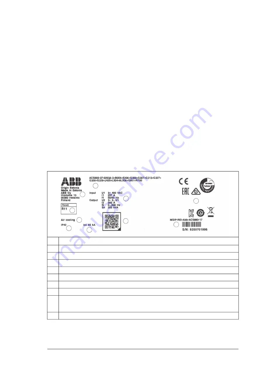
Type designation label
The type designation label includes an IEC and UL (NEC) rating, appropriate markings, a
type designation and a serial number, which allow identification of each unit.
Quote the complete type designation and serial number when contacting technical support.
A sample label is shown below.
1
3
4
5
2
6
7
8
9
10
Type designation, see section
Type designation key (page 58)
1
Manufacturing address
2
Frame size
3
Cooling method
4
Degree of protection
5
Ratings
6
Short-circuit withstand strength
7
Valid markings
8
Serial number. The first digit of the serial number refers to the manufacturing plant. The next four digits
refer to the unit’s manufacturing year and week, respectively. The remaining digits complete the serial
number so that there are no two units with the same number.
9
Link to product information
10
Operation principle and hardware description 57
Summary of Contents for ACS880-37
Page 1: ... ABB INDUSTRIAL DRIVES ACS880 37 drives 45 400 kW 60 450 hp Hardware manual ...
Page 2: ......
Page 4: ......
Page 26: ...26 ...
Page 83: ...Mechanical installation 83 10 ...
Page 84: ...84 ...
Page 126: ... B055 a X504 126 Electrical installation ...
Page 144: ...144 ...
Page 150: ...150 ...
Page 152: ...152 ...
Page 160: ... 160 Maintenance ...
Page 196: ... 196 Maintenance ...
Page 232: ...R8 IP22 UL Type 1 and option B054 IP42 UL Type 1 Filtered 232 Dimension drawings ...
Page 233: ...R8 IP54 UL Type 12 option B055 option C129 Dimension drawings 233 ...
Page 235: ...R8 IP22 UL Type 1 and IP42 UL Type 1 Filtered option B054 option E206 Dimension drawings 235 ...
Page 236: ...R8 IP22 UL Type 1 option E202 236 Dimension drawings ...
Page 237: ...R11 IP22 UL Type 1 and IP42 UL Type 1 Filtered option B054 Dimension drawings 237 ...
Page 238: ...R11 IP54 UL Type 12 option B055 238 Dimension drawings ...
Page 240: ...R11 IP54 UL Type 12 option B055 option C128 240 Dimension drawings ...
Page 241: ...R11 IP54 UL Type 12 option B055 option C129 Dimension drawings 241 ...
Page 242: ...R11 IP54 UL Type 12 option B055 options C129 H350 H352 242 Dimension drawings ...
Page 243: ...R11 IP22 UL Type 1 and IP42 UL Type 1 Filtered option B054 option D150 Dimension drawings 243 ...
Page 245: ...R11 IP22 UL Type 1 and IP42 UL Type 1 Filtered option B054 option E206 Dimension drawings 245 ...
Page 246: ...R11 IP22 UL Type 1 option E202 246 Dimension drawings ...
Page 267: ... Declaration of conformity The Safe torque off function 267 ...
Page 268: ...268 The Safe torque off function ...
Page 280: ...280 ...

