Miscellaneous
■
Cable duct in the floor below the cabinet
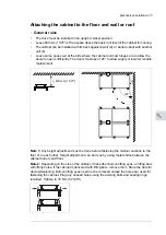
A cable duct can be constructed below the 500 mm wide middle part of the cabinet. The
cabinet weight lies on the two 50 mm wide transverse sections which the floor must carry.
Prevent the cooling air flow from the cable duct to the cabinet by bottom plates. To ensure
the degree of protection for the cabinet, use the original bottom plates delivered with the
unit. With user-defined cable entries, take care of the degree of protection, fire protection
and EMC compliance.
500 (19.68”)
50 (1.97”)
500
(
19.
68
”)
50 (1.97”)
■
Arc welding
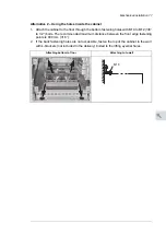
ABB does not recommend attaching the cabinet by arc welding. However, if arc welding is
the only option, connect the return conductor of the welding equipment to the cabinet frame
at the bottom within 0.5 meters (1’6”) of the welding point.
Note:
The thickness of the zinc plating of the cabinet frame is 100…200 micrometers
(4…8 mil).
WARNING!
Make sure that the return wire is connected correctly. Welding current must not
return via any component or cabling of the drive. If the welding return wire is
connected improperly, the welding circuit can damage electronic circuits in the
cabinet.
WARNING!
Do not inhale the welding fumes.
■
Air inlet through the bottom of cabinet (C128)
Drives with air intake through the bottom of the cabinet (C128) are intended for
installation on an air duct in the floor. Each cubicle (except top entry adapter and joining
cubicles) have an inlet through the bottom plate. The option also adds a 130 mm deep inlet
area at the back of the cubicle.
An example of the air inlets in the cabinet bottom plate is shown below. Refer also to the
dimension drawings delivered with the drive.
Mechanical installation 79
10
Summary of Contents for ACS880-37
Page 1: ... ABB INDUSTRIAL DRIVES ACS880 37 drives 45 400 kW 60 450 hp Hardware manual ...
Page 2: ......
Page 4: ......
Page 26: ...26 ...
Page 83: ...Mechanical installation 83 10 ...
Page 84: ...84 ...
Page 126: ... B055 a X504 126 Electrical installation ...
Page 144: ...144 ...
Page 150: ...150 ...
Page 152: ...152 ...
Page 160: ... 160 Maintenance ...
Page 196: ... 196 Maintenance ...
Page 232: ...R8 IP22 UL Type 1 and option B054 IP42 UL Type 1 Filtered 232 Dimension drawings ...
Page 233: ...R8 IP54 UL Type 12 option B055 option C129 Dimension drawings 233 ...
Page 235: ...R8 IP22 UL Type 1 and IP42 UL Type 1 Filtered option B054 option E206 Dimension drawings 235 ...
Page 236: ...R8 IP22 UL Type 1 option E202 236 Dimension drawings ...
Page 237: ...R11 IP22 UL Type 1 and IP42 UL Type 1 Filtered option B054 Dimension drawings 237 ...
Page 238: ...R11 IP54 UL Type 12 option B055 238 Dimension drawings ...
Page 240: ...R11 IP54 UL Type 12 option B055 option C128 240 Dimension drawings ...
Page 241: ...R11 IP54 UL Type 12 option B055 option C129 Dimension drawings 241 ...
Page 242: ...R11 IP54 UL Type 12 option B055 options C129 H350 H352 242 Dimension drawings ...
Page 243: ...R11 IP22 UL Type 1 and IP42 UL Type 1 Filtered option B054 option D150 Dimension drawings 243 ...
Page 245: ...R11 IP22 UL Type 1 and IP42 UL Type 1 Filtered option B054 option E206 Dimension drawings 245 ...
Page 246: ...R11 IP22 UL Type 1 option E202 246 Dimension drawings ...
Page 267: ... Declaration of conformity The Safe torque off function 267 ...
Page 268: ...268 The Safe torque off function ...
Page 280: ...280 ...


