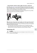
...
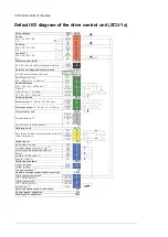
AI1+
AI1-
AO1
AGND
2
1
3
T
T
T
One, two or three Pt100, Pt1000 or PTC sensors; or one KTY84 sensor
1
Set the input type to voltage with J1 for analog input AI1 or with J2 for analog input AI2. Set the appropriate
analog input unit to V (volt) in parameter group 12 Standard AI.
2
Select the excitation mode in parameter group 13 Standard AO.
3
1)
Set the input type to voltage with the appropriate switch or jumper on the inverter control
unit. Make the corresponding setting in the inverter unit control program in parameter group
12 Standard AI
.
2)
Select the excitation mode in parameter group
13 Standard AO
of inverter unit control
program.
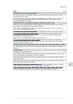
WARNING!
As the inputs pictured above are not insulated according to IEC/EN 60664, the
connection of the motor temperature sensor requires double or reinforced insulation
between motor live parts and the sensor. If the assembly does not fulfill the
requirement, the I/O board terminals must be protected against contact and must
not be connected to other equipment or the temperature sensor must be isolated
from the I/O terminals.
■
DIIL input
The DIIL input is used for the connection of safety circuits. The input is parametrized to stop
the unit when the input signal is lost.
Note:
This input is NOT SIL or Pl certified.
■
The XD2D connector
The XD2D connector provides an RS-485 connection that can be used for
•
basic master/follower communication with one master drive and multiple followers,
•
fieldbus control through the embedded fieldbus interface (EFB), or
•
drive-to-drive (D2D) communication implemented by application programming.
See the firmware manual of the drive for the related parameter settings.
Enable bus termination on the units at the ends of the drive-to-drive link. Disable bus
termination on the intermediate units.
Use shielded twisted-pair cable with a twisted pair for data and a wire or another pair for
signal ground (nominal impedance 100 to 165 ohm, for example Belden 9842) for the wiring.
For best immunity, ABB recommends high quality cable. Keep the cable as short as possible.
Avoid unnecessary loops and parallel runs near power cables such as motor cables.
The following diagram shows the wiring between control units.
Control units of the drive 139
Summary of Contents for ACS880-37
Page 1: ... ABB INDUSTRIAL DRIVES ACS880 37 drives 45 400 kW 60 450 hp Hardware manual ...
Page 2: ......
Page 4: ......
Page 26: ...26 ...
Page 83: ...Mechanical installation 83 10 ...
Page 84: ...84 ...
Page 126: ... B055 a X504 126 Electrical installation ...
Page 144: ...144 ...
Page 150: ...150 ...
Page 152: ...152 ...
Page 160: ... 160 Maintenance ...
Page 196: ... 196 Maintenance ...
Page 232: ...R8 IP22 UL Type 1 and option B054 IP42 UL Type 1 Filtered 232 Dimension drawings ...
Page 233: ...R8 IP54 UL Type 12 option B055 option C129 Dimension drawings 233 ...
Page 235: ...R8 IP22 UL Type 1 and IP42 UL Type 1 Filtered option B054 option E206 Dimension drawings 235 ...
Page 236: ...R8 IP22 UL Type 1 option E202 236 Dimension drawings ...
Page 237: ...R11 IP22 UL Type 1 and IP42 UL Type 1 Filtered option B054 Dimension drawings 237 ...
Page 238: ...R11 IP54 UL Type 12 option B055 238 Dimension drawings ...
Page 240: ...R11 IP54 UL Type 12 option B055 option C128 240 Dimension drawings ...
Page 241: ...R11 IP54 UL Type 12 option B055 option C129 Dimension drawings 241 ...
Page 242: ...R11 IP54 UL Type 12 option B055 options C129 H350 H352 242 Dimension drawings ...
Page 243: ...R11 IP22 UL Type 1 and IP42 UL Type 1 Filtered option B054 option D150 Dimension drawings 243 ...
Page 245: ...R11 IP22 UL Type 1 and IP42 UL Type 1 Filtered option B054 option E206 Dimension drawings 245 ...
Page 246: ...R11 IP22 UL Type 1 option E202 246 Dimension drawings ...
Page 267: ... Declaration of conformity The Safe torque off function 267 ...
Page 268: ...268 The Safe torque off function ...
Page 280: ...280 ...


