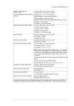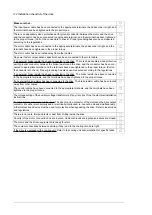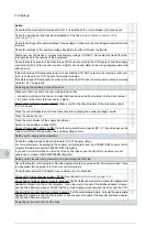
Action
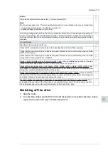
Close the main switch-disconnector [Q1.1] or main breaker [Q1].
Note:
Do not use excessive force. The main switch-disconnector (or main breaker) can only be closed when
• the main input terminals [L1, L2, L3] are powered, and
• auxiliary voltage is switched on [Q21], and
Turn the operating switch (S21) to the ON (1) position to activate the run enable signal. Depending on
control source settings, this may also close the main contactor (if present). If a main contactor is present
and does not close, refer to the circuit diagrams delivered by the drive as well as the appropriate firmware
manuals.
On-load checks
Start the motor to perform the ID run.
Check that the cooling fans rotate freely in the right direction, and the air flows upwards.
Check that the motor starts. stops and follows the speed reference in the correct direction when controlled
with the control panel.
Check that the motor starts. stops and follows the speed reference in the correct direction when controlled
through the customer-specific I/O or fieldbus.
Drives in which the Safe torque off control circuit is in use: Test and validate the operation of the Safe
torque off function. See section
Start-up including acceptance test (page 191)
Drives with an emergency stop circuit (oQ951, +Q952, +Q963, +Q964, +Q978, +Q979): Test
and validate the operation of the emergency-stop circuit. See the delivery specific circuit diagrams and
wiring, start-up and operating instructions of the option.
Drives with the Prevention of unexpected start-up with safety relay (Q957): Test and validate
the operation of the Prevention of unexpected start-up circuit. See the delivery specific circuit diagrams
and wiring, start-up and operating instructions of the option.
Test and validate the operation of Prevention of unexpected start with FSO-xx (Q950): Test
and validate the operation of the Prevention of unexpected start-up circuit. See the delivery specific
circuit diagrams and wiring, start-up and operating instructions of the option.
Switching off the drive
1.
Stop the motor.
2.
Turn the Run enable switch (S21) to the off (0) position to deactivate the Run enable
signal and to switch the main contactor/breaker off.
Start-up 115
12
Summary of Contents for ACS880-37LC
Page 1: ... ABB INDUSTRIAL DRIVES ACS880 37LC drives Hardware manual ...
Page 2: ......
Page 4: ......
Page 78: ...78 ...
Page 116: ...116 ...
Page 134: ...5 Set the real time clock 134 Maintenance ...
Page 144: ...144 ...
Page 167: ... Dimension drawing examples ACS880 37LC 0390A 7 with main contactor Dimensions 167 ...
Page 169: ...ACS880 37LC 1270A 7 with common motor terminal cubicle Dimensions 169 ...
Page 170: ...ACS880 37LC 1940A 7 with common motor terminal cubicle 170 Dimensions ...
Page 172: ...Location and size of input terminals Contact ABB for details 172 Dimensions ...
Page 174: ...Inverter module cubicle with two R8i modules bottom cable exit 174 Dimensions ...
Page 175: ...Inverter module cubicle with three R8i modules bottom cable exit Dimensions 175 ...
Page 176: ...Brake chopper cubicle D150 176 Dimensions ...
Page 178: ...Cubicle width 300 mm top cable exit 178 Dimensions ...
Page 179: ...Cubicle width 400 mm bottom cable exit Dimensions 179 ...
Page 180: ...Cubicle width 400 mm top cable exit 180 Dimensions ...
Page 181: ...Cubicle width 600 mm bottom cable exit Dimensions 181 ...
Page 182: ...Cubicle width 600 mm top cable exit 182 Dimensions ...
Page 198: ...198 ...
Page 200: ...200 ...

