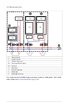
Draining the internal cooling circuit
The modules in each cubicle can be drained through the drain valves without draining the
whole internal cooling circuit.
WARNING!
Hot, pressurized coolant can be present in the cooling circuit. Do not work on the
cooling circuit before the pressure is released by stopping the pumps and draining
coolant.
1.
Attach hoses to each drain valve in the cubicle to be drained. Lead the hoses into a
suitable container. Make sure the ends of the hoses are not immersed in coolant at any
point so that air can displace the coolant in the system.
2.
Open the drain valves. Wait until all coolant has drained.
Note:
Draining coolant into the sewer system is not allowed.
3.
If required, dry the piping with compressed oil-free air of less than 6 bar.
4.
If the drive is to be stored in temperatures below 0 °C (32 °F),
•
dry the cooling circuit with air,
•
fill the cooling circuit with coolant specified under
Coolant specification (page 140)
•
drain the cooling circuit again.
Maintenance intervals
As a general rule, the quality of the coolant should be checked at intervals of two years.
This can be done by distributors of Antifrogen® L (see
) if a 250 milliliter
sample is provided.
Technical data
■
Coolant specification
Coolant type
Antifrogen® L (by Clariant International Ltd,
) 25% or 50% water mixture,
available from Clariant distributors and ABB Service representatives.
Antifrogen® L 25% mixture is usable in storage temperatures down to -16 °C (3.2 °F).
Antifrogen® L 50% mixture is usable in storage temperatures down to -40 °C (-40 °F).
Note that operation below 0 °C (32 °F) is not allowed regardless of the freezing point of the
coolant.
WARNING!
The warranty does not cover damage occurring from use of improper coolant.
■
Temperature limits
Ambient temperature:
See the technical data of the drive/unit.
Freeze protection:
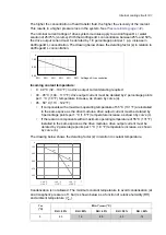
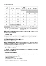
The freezing point of the coolant is determined by the concentration of
heat transfer fluid in the mixture.
140 Internal cooling circuit
Summary of Contents for ACS880-37LC
Page 1: ... ABB INDUSTRIAL DRIVES ACS880 37LC drives Hardware manual ...
Page 2: ......
Page 4: ......
Page 78: ...78 ...
Page 116: ...116 ...
Page 134: ...5 Set the real time clock 134 Maintenance ...
Page 144: ...144 ...
Page 167: ... Dimension drawing examples ACS880 37LC 0390A 7 with main contactor Dimensions 167 ...
Page 169: ...ACS880 37LC 1270A 7 with common motor terminal cubicle Dimensions 169 ...
Page 170: ...ACS880 37LC 1940A 7 with common motor terminal cubicle 170 Dimensions ...
Page 172: ...Location and size of input terminals Contact ABB for details 172 Dimensions ...
Page 174: ...Inverter module cubicle with two R8i modules bottom cable exit 174 Dimensions ...
Page 175: ...Inverter module cubicle with three R8i modules bottom cable exit Dimensions 175 ...
Page 176: ...Brake chopper cubicle D150 176 Dimensions ...
Page 178: ...Cubicle width 300 mm top cable exit 178 Dimensions ...
Page 179: ...Cubicle width 400 mm bottom cable exit Dimensions 179 ...
Page 180: ...Cubicle width 400 mm top cable exit 180 Dimensions ...
Page 181: ...Cubicle width 600 mm bottom cable exit Dimensions 181 ...
Page 182: ...Cubicle width 600 mm top cable exit 182 Dimensions ...
Page 198: ...198 ...
Page 200: ...200 ...

