134 Technical data
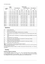
Ratings
Definitions
Derating
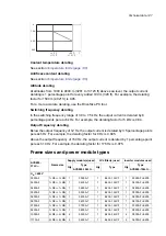
Ambient temperature derating
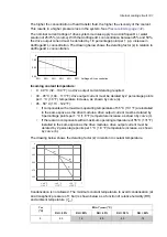
In the temperature range +45…55 °C (+113…131 °F), the rated output current is derated
by 0.5 percentage points for every added 1 °C (1.8 °F). The output current can be
calculated by multiplying the current given in the rating table by the derating factor (
k
):
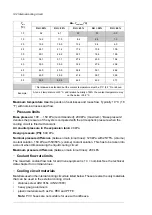
Module type
ACS880-304LC...
No overload use
Light overload
use
Heavy-duty
use
I
1
I
2
I
max
S
n
I
max
P
n
I
Ld
P
Ld
I
Hd
P
Hd
A (AC) A (DC) A (DC)
kVA
A (AC) kW (DC) A (DC)
kW
(DC)
A (DC)
kW
(DC)
U
N
= 690 V
-0820A-7+A019
820
1000
1400
980
1143
932
960
895
800
745
-1540A-7+A019
1540
1880
2632
1840
2149
1752
1805
1682
1504
1401
-2290A-7+A019
2290
2805
3927
2737
3206
2614
2693
2509
2244
2091
-3040A-7+A019
3040
3720
5208
3633
4252
3466
3571
3328
2976
2773
3AXD00000601909.XLS
Nominal ratings
U
N
Nominal input voltage. For
U
1
, see
Electrical power network specification
on page
139
. For
U
2
, see
DC connection data
on page
139
.
I
1
Continuous rms input (AC) current. No overload capability at the coolant temperature of 40 °C
(104 °F) and air temperature of 45 °C (113 °F).
I
2
Continuous rms output (DC) current. No overload capability at the coolant temperature of 40 °C
(104 °F) and air temperature of 45 °C (113 °F).
I
max
Maximum output (DC) current. Available for 10 s at start, otherwise as long as allowed by module
temperature.
S
n
Nominal apparent (AC) power
I
max
Maximum input (AC) current
P
n
Nominal output (DC) power
Light-overload use (50% overload capability) ratings
I
Ld
Continuous current. 50% overload is allowed for one minute every 5 minutes.
P
Ld
Output power in light-overload use
Heavy-duty use (50% overload capability) ratings
I
Hd
Continuous current. 50% overload is allowed for one minute every 5 minutes.
P
Hd
Output power in heavy-duty use
T
1.00
0.95
+45 °C
+113 °F
+55 °C
+131 °F
k
0.90
ACS880-304LC ACS880-104LC_ambient temp derating curve.pdf
Coolant temperature derating
See section
Antifreeze content derating
See section
Altitude derating
At altitudes from 1000 to 4000 m (3281 to 13123 ft) above sea level, the output current
derating is 1 percentage point for every added 100 m (328 ft). For example, the derating
factor for 1500 m (4921 ft) is 0.95.
For a more accurate derating, use the DriveSize PC tool.
Switching frequency derating
In the switching frequency range of 3.0 to 7.5 kHz, the output current is derated by 8
percentage points per each kHz. For example, the derating factor for 5 kHz is 0.84.
Output frequency derating
Below the output frequency of 12 Hz, the output current is derated by 3.5 percentage points
per each Hz. For example, the derating factor for 9 Hz is 0.895.
Above the output frequency of 150 Hz, the output current is derated by 1 percentage point
per each 10 Hz. For example, the derating factor for 175 Hz is 0.975.
Frame sizes and power module types
Inverter modules used
LCL filter(s) used
Supply module(s) used
Frame size
ACS880-
37LC-…
Type
ACS880-104LC-…
Qty
Type
Qty
Type
ACS880-104LC-…
Qty
U
N
= 690 V
0390A-7+E205
1
BLCL-15LC-7
1
0390A-7
1
1×R8i + 1×R8i
0390A-7
0430A-7+E205
1
BLCL-15LC-7
1
0430A-7
1
1×R8i + 1×R8i
0430A-7
0480A-7+E205
1
BLCL-15LC-7
1
0480A-7
1
1×R8i + 1×R8i
0480A-7
0530A-7+E205
1
BLCL-15LC-7
1
0530A-7
1
1×R8i + 1×R8i
0520A-7
0600A-7+E205
1
BLCL-15LC-7
1
0600A-7
1
1×R8i + 1×R8i
0600A-7
0670A-7+E205
1
BLCL-15LC-7
1
0670A-7
1
1×R8i + 1×R8i
0670A-7
0750A-7+E205
1
BLCL-15LC-7
1
0750A-7
1
1×R8i + 1×R8i
0750A-7
0850A-7+E205
1
BLCL-15LC-7
1
0850A-7
1
1×R8i + 1×R8i
0830A-7
0530A-7+E205
2
BLCL-24LC-7
1
0530A-7
2
2×R8i + 2×R8i
1000A-7
0600A-7+E205
2
BLCL-24LC-7
1
0600A-7
2
2×R8i + 2×R8i
1170A-7
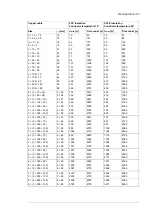
Technical data 147
Summary of Contents for ACS880-37LC
Page 1: ... ABB INDUSTRIAL DRIVES ACS880 37LC drives Hardware manual ...
Page 2: ......
Page 4: ......
Page 78: ...78 ...
Page 116: ...116 ...
Page 134: ...5 Set the real time clock 134 Maintenance ...
Page 144: ...144 ...
Page 167: ... Dimension drawing examples ACS880 37LC 0390A 7 with main contactor Dimensions 167 ...
Page 169: ...ACS880 37LC 1270A 7 with common motor terminal cubicle Dimensions 169 ...
Page 170: ...ACS880 37LC 1940A 7 with common motor terminal cubicle 170 Dimensions ...
Page 172: ...Location and size of input terminals Contact ABB for details 172 Dimensions ...
Page 174: ...Inverter module cubicle with two R8i modules bottom cable exit 174 Dimensions ...
Page 175: ...Inverter module cubicle with three R8i modules bottom cable exit Dimensions 175 ...
Page 176: ...Brake chopper cubicle D150 176 Dimensions ...
Page 178: ...Cubicle width 300 mm top cable exit 178 Dimensions ...
Page 179: ...Cubicle width 400 mm bottom cable exit Dimensions 179 ...
Page 180: ...Cubicle width 400 mm top cable exit 180 Dimensions ...
Page 181: ...Cubicle width 600 mm bottom cable exit Dimensions 181 ...
Page 182: ...Cubicle width 600 mm top cable exit 182 Dimensions ...
Page 198: ...198 ...
Page 200: ...200 ...


