•
NC: 230 V, 1 A
•
NO: 230 V, 3 A
•
Switching capacity, DC (IEC/EN 60947-5-1 DC 13):
•
NC / NO: 24 V, 2 A
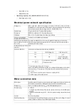
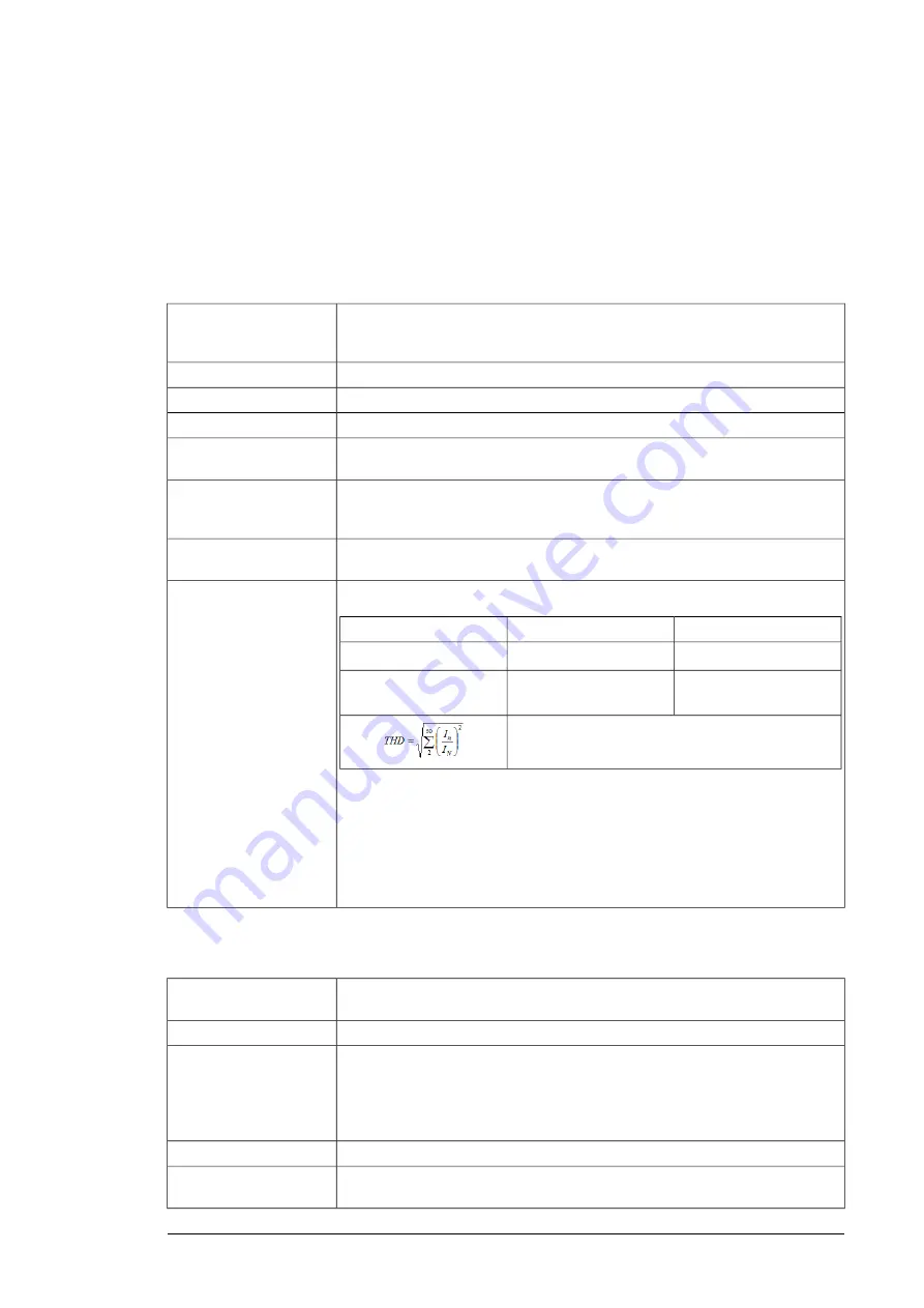
Electrical power network specification
690 V units: 525…690 V AC 3-phase ± 10% (525…600 V AC ± 10% in UL/CSA
installations, or corner-grounded TN systems). This is indicated in the type desig-
nation label as typical input voltage levels (3~ 525/600/690 V AC).
Voltage (
U
1
)
TN (grounded) and IT (ungrounded) systems
Network type
50/60 Hz, variation ± 5% of nominal frequency
Frequency
Max. ± 3% of nominal phase-to-phase input voltage
Imbalance
Contact your local ABB representative.
Short-circuit withstand
strength (IEC/EN 61439-1)
The drive is suitable for use on a circuit capable of delivering not more than
100,000 rms symmetrical amperes at 600 V maximum when the input cable is
protected with class T fuses.
Short-circuit current protec-
tion (UL 508A, CSA C22.2
No. 14-13)
0.99
Fundamental power factor
(cos phi
1
)
Harmonics are below the limits defined in IEEE519.
Harmonic distortion
THD Current [%]
THD Voltage [%]
R
sc
2.5
1)
3
20
2.5 (4.0 with types -
0.8
100
I
n
n
th
harmonic component
I
N
nominal current
1) Other loads may influence the THD value.
THD = Total Harmonic Distortion (THD). The voltage THD depends on the short-
circuit ratio (
R
sc
). The spectrum of the distortion also contains interharmonics.
R
sc
=
I
sc
/
I
N
I
sc
= short-circuit current at point of common coupling (PCC)
I
N
= IGBT supply unit nominal current
Motor connection data
Asynchronous AC induction motors, permanent magnet synchronous motors and
AC induction servomotors, ABB synchronous reluctance (SynRM) motors
Motor types
0 to
U
1
, 3-phase symmetrical,
U
max
at the field weakening point
Voltage (
U
2
)
0…500 Hz
Frequency (
f
2
)
• For higher operational output frequencies, please contact your local ABB repres-
entative.
• Operation outside the range of 12…150 Hz requires derating. See section Derat-
ing.
See the rating tables.
Current
3 kHz (typical). The switching frequency can vary per frame and voltage. For exact
values, please contact your local ABB representative.
Switching frequency
Technical data 155
Summary of Contents for ACS880-37LC
Page 1: ... ABB INDUSTRIAL DRIVES ACS880 37LC drives Hardware manual ...
Page 2: ......
Page 4: ......
Page 78: ...78 ...
Page 116: ...116 ...
Page 134: ...5 Set the real time clock 134 Maintenance ...
Page 144: ...144 ...
Page 167: ... Dimension drawing examples ACS880 37LC 0390A 7 with main contactor Dimensions 167 ...
Page 169: ...ACS880 37LC 1270A 7 with common motor terminal cubicle Dimensions 169 ...
Page 170: ...ACS880 37LC 1940A 7 with common motor terminal cubicle 170 Dimensions ...
Page 172: ...Location and size of input terminals Contact ABB for details 172 Dimensions ...
Page 174: ...Inverter module cubicle with two R8i modules bottom cable exit 174 Dimensions ...
Page 175: ...Inverter module cubicle with three R8i modules bottom cable exit Dimensions 175 ...
Page 176: ...Brake chopper cubicle D150 176 Dimensions ...
Page 178: ...Cubicle width 300 mm top cable exit 178 Dimensions ...
Page 179: ...Cubicle width 400 mm bottom cable exit Dimensions 179 ...
Page 180: ...Cubicle width 400 mm top cable exit 180 Dimensions ...
Page 181: ...Cubicle width 600 mm bottom cable exit Dimensions 181 ...
Page 182: ...Cubicle width 600 mm top cable exit 182 Dimensions ...
Page 198: ...198 ...
Page 200: ...200 ...

