■
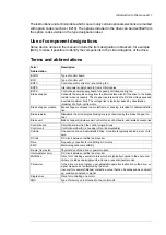
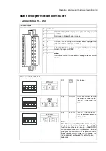
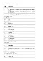
Fibre optic connectors
Description
Name
BSFC
V50
V60
BFPS
V30
V40
BCU
V10
V20
Charging controller connection (F286).
BSFC
Fan control connection (to fan control box).
BFPS
Control unit connection.
BCU
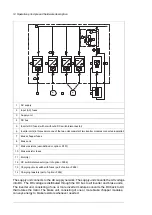
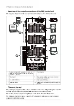
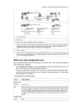
Overview of power and control connections
The diagram below shows the power and control connections of the brake unit consisting
of one 3-phase brake chopper module. For parallel-connected brake chopper modules, the
brake resistors are connected to each brake chopper module also as shown below. Each
parallel-connected brake chopper module has a dedicated control unit.
9
:
8
'&
'&
3(
'&
'&
t
t
t
5
5
5
9
',
97
95
9
9
5
5
5
20 Operation principle and hardware description
Summary of Contents for ACS880-607 Series
Page 1: ... ABB INDUSTRIAL DRIVES ACS880 607 3 phase brake units Hardware manual ...
Page 2: ......
Page 4: ......
Page 8: ...8 ...
Page 12: ...12 ...
Page 30: ...30 ...
Page 32: ...32 ...
Page 36: ...36 ...
Page 44: ...44 ...
Page 54: ...54 ...
Page 62: ...62 ...
Page 66: ...66 Maintenance ...
Page 82: ...Dimension drawing bottom exit 82 Dimension drawings ...
Page 83: ...Dimension drawings 83 ...
Page 84: ...Dimension drawing top exit 84 Dimension drawings ...
Page 85: ... Dimension drawings 85 ...
Page 86: ......


