■
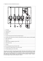
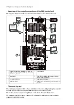
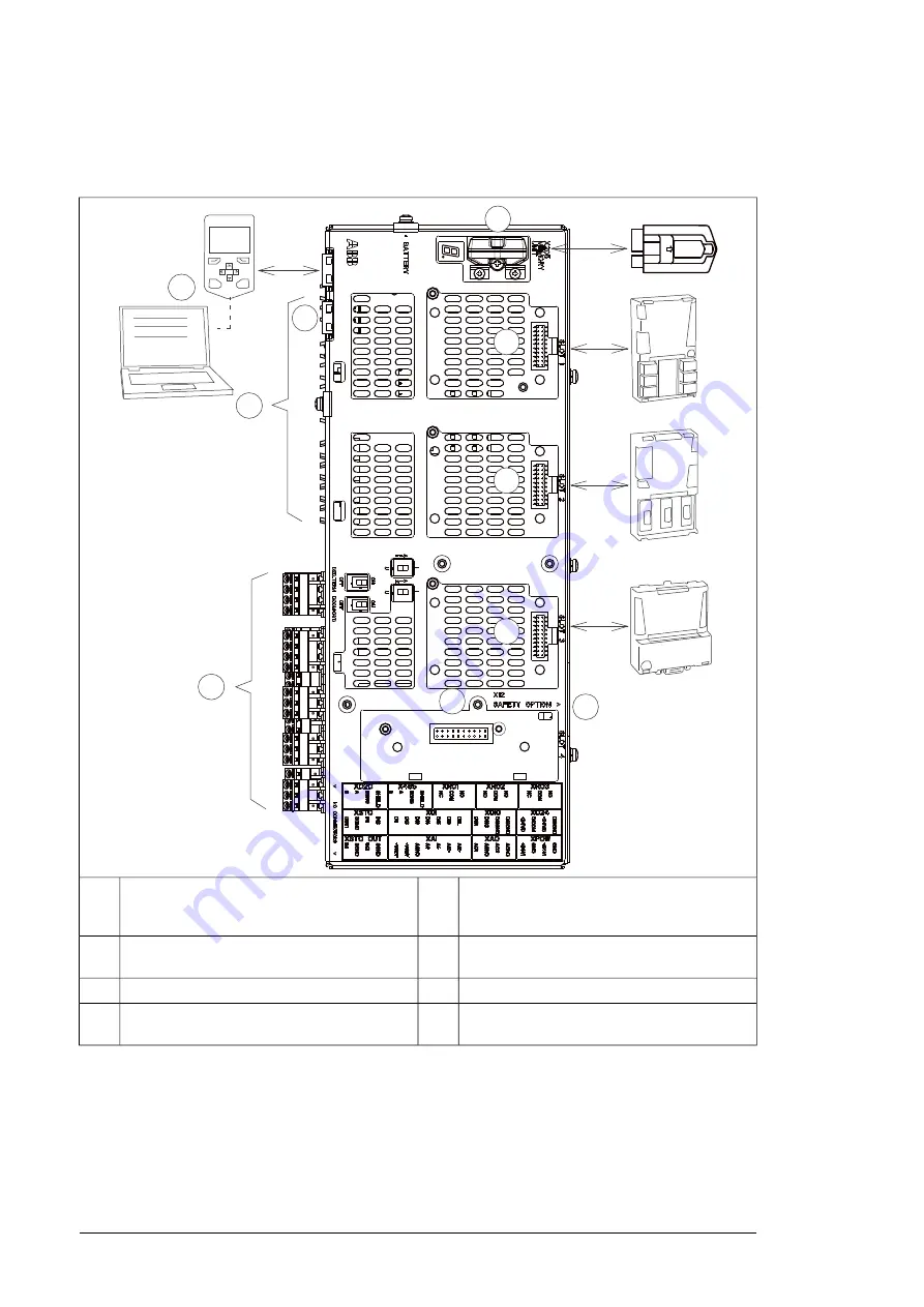
Overview of the control connections of the BCU control unit
The diagram shows the control connections and interfaces of the BCU control unit.
1
2
3
4
5
6
7
FXX
FXX
FXXX
8
CLOSE
9
10
Control panel.
7
Analog and digital I/O extension modules and
fieldbus communication modules can be inserted
into slots 1, 2 and 3.
1
2
3
Fiber optic links to power modules (inverter,
supply, brake or converter)
8
Memory unit
4
Ethernet port. Not in use.
9
Slot 4 for RDCO-0x
5
Safety option interface. Only in use for the invert-
er units.
10
Terminal blocks.
6
■
The control panel
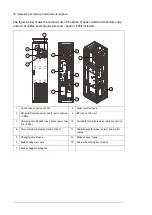
The control panel (J400) is the user interface of the brake unit, providing the essential
controls such as reset, and the parameter settings for the control program.
The control panel is mounted on a platform on the brake chopper cubicle door.
For details on the control panel, see
ACS-AP-x Assistant control panels user’s manual
(3AUA0000085685 [English]).
22 Operation principle and hardware description
Summary of Contents for ACS880-607 Series
Page 1: ... ABB INDUSTRIAL DRIVES ACS880 607 3 phase brake units Hardware manual ...
Page 2: ......
Page 4: ......
Page 8: ...8 ...
Page 12: ...12 ...
Page 30: ...30 ...
Page 32: ...32 ...
Page 36: ...36 ...
Page 44: ...44 ...
Page 54: ...54 ...
Page 62: ...62 ...
Page 66: ...66 Maintenance ...
Page 82: ...Dimension drawing bottom exit 82 Dimension drawings ...
Page 83: ...Dimension drawings 83 ...
Page 84: ...Dimension drawing top exit 84 Dimension drawings ...
Page 85: ... Dimension drawings 85 ...
Page 86: ......

