background image

2) This input only acts as a true Safe torque off input in inverter control units. In other applications (such as a supply or brake

unit), de-energizing the IN1 and/or IN2 terminal will stop the unit but not constitute a true safety function.

3) Total load capacity of these outputs is 4.8 W (200 mA at 24 V) minus the power taken by DIO1 and DIO2.
4) Determines whether DICOM is separated from DIOGND (ie, common reference for digital inputs floats). ON: DICOM

connected to DIOGND. OFF: DICOM and DIOGND separate.

5) Current [0(4)…20 mA,

R

in

= 100 ohm] or voltage [0(2)…10 V,

R

in

> 200 kohm] input selected by switch AI2. Change of

setting requires reboot of control unit.

6) Current [0(4)…20 mA,

R

in

= 100 ohm] or voltage [0(2)…10 V,

R

in

> 200 kohm] input selected by switch AI1. Change of

setting requires reboot of control unit.

External power supply for the control unit (XPOW)

The control unit is powered from a 24 V DC, 2 A supply through terminal block XPOW. With
a type BCU control unit, a second supply can be connected to the same terminal block for
redundancy.

Using an external supply is recommended if

• the control unit needs to be kept operational during input power breaks, for example,

because of continuous fieldbus communication

• immediate restart is needed after a power break (that is, no control unit power-up delay

is allowed).

The X485 connector

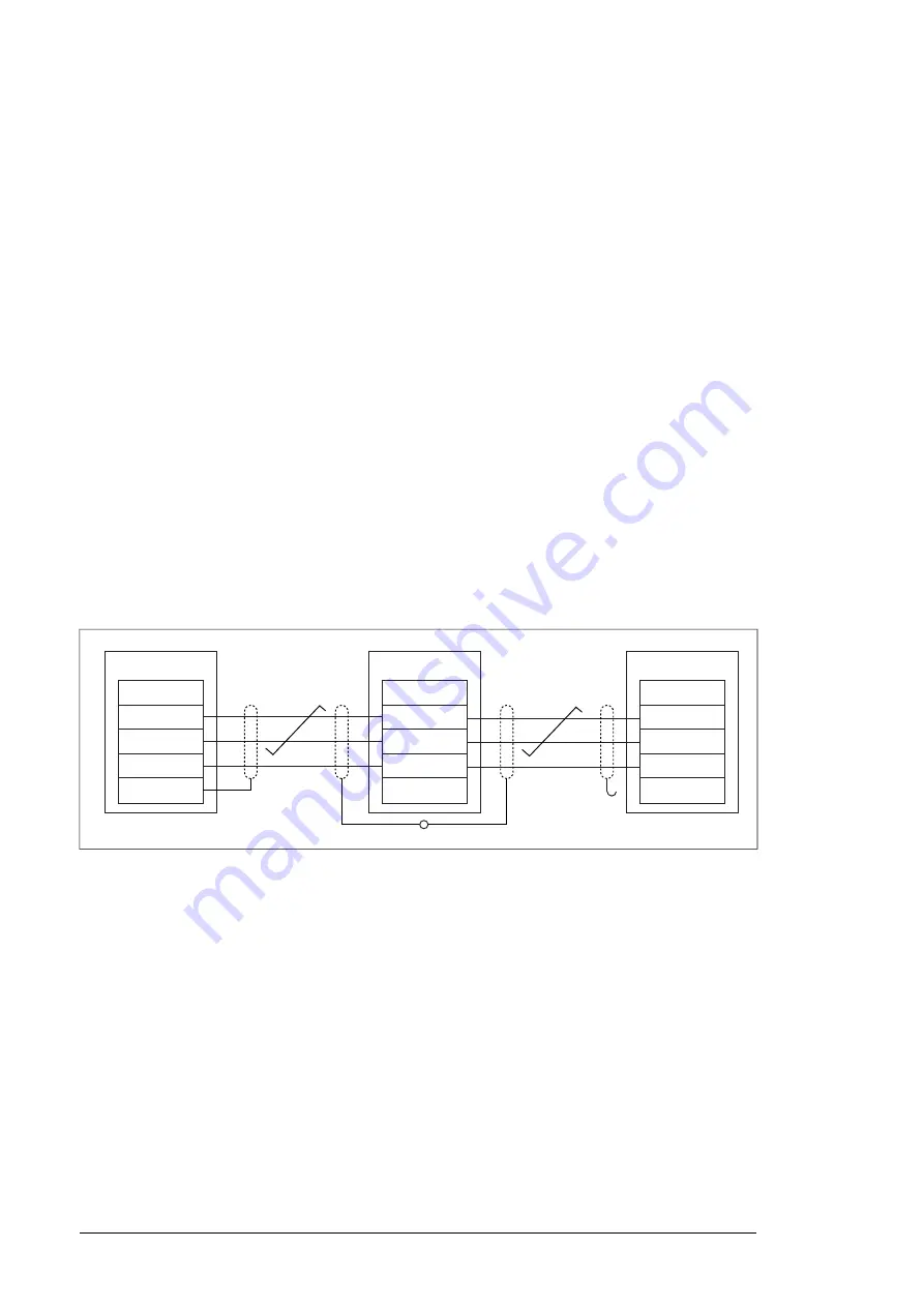
The X485 provides a connection for optional CIO-01 I/O module. The following diagram
shows the wiring for the CIO module.

BCU

CIO

CIO

X485

B

A

BGND

SHIELD

X485

B

A

GND

SHIELD

X485

B

A

GND

SHIELD

Safe torque off (XSTO, XSTO OUT)

Note:

The XSTO input only acts as a true Safe torque off input on the inverter control unit.

De-energizing the IN1 and/or IN2 terminals of other units (supply, DC/DC converter, or brake
unit) will stop the unit but not constitute a true safety function.

FSO-xx safety functions module connection (X12)

See the user manual of the FSO-xx module. Note that the FSO-xx safety functions module
is not in use in supply, DC/DC converter or brake units.

SDHC memory card slot

The BCU-x2 has an on-board data logger that collects real-time data from the power modules
to help fault tracing and analysis. The data is stored onto the SDHC memory card inserted
into the SD CARD slot and can be analyzed by ABB service personnel.

52 The control unit

Summary of Contents for ACS880-607LC

Page 1: ... ABB INDUSTRIAL DRIVES ACS880 607LC 3 phase dynamic brake units Hardware manual ...

Page 2: ......

Page 3: ...ACS880 607LC 3 phase dynamic brake units Hardware manual Table of contents 4 Electrical installation 7 Start up 3AXD50000581627 Rev A EN EFFECTIVE 2020 10 02 ...

Page 4: ......

Page 5: ... drawing brake module R8i 20 Module layout 21 Coolant connectors 21 Connectors X50 X59 22 Fiber optic connectors 23 Overview of power and control connections 24 Brake unit control devices 24 Overview of the control connections of the BCU control unit 25 The control panel 25 Control by PC tools 25 Fieldbus control 25 DC switch and charging switch 26 Type designation labels 26 Type designation label...

Page 6: ...nnection procedure 41 Grounding the outer shields of the control cables at the cabinet entry 43 Routing the control cables inside the cabinet 43 Connecting control cabling 45 Connecting a PC 5 The control unit 47 Contents of this chapter 47 General 48 BCU x2 layout 50 Default I O diagram of the brake control unit 52 External power supply for the control unit XPOW 52 The X485 connector 52 Safe torq...

Page 7: ...1 Removing the module 74 Reinstalling the module 74 Capacitors 74 Reforming the capacitors 74 Fuses 74 Replacing the brake chopper fuses 75 Replacing the resistor fuses 77 Control panel 77 Cleaning the control panel 77 Replacing the battery 77 Memory unit 77 Replacing the memory unit 11 Internal cooling circuit 79 Contents of this chapter 79 Applicability 79 Internal cooling system 81 Connection t...

Page 8: ...pace requirements 94 Losses cooling data and noise 94 Terminal and cable entry data for the resistor cables 95 Bottom entry and exit of cables 97 Top entry and exit of cables 98 Tightening torques 98 Electrical connections 98 Mechanical connections 98 Insulation supports 98 Cable lugs 98 Typical resistor cable sizes 99 Maximum cable length 99 Resistor connection 99 Control unit board connection da...

Page 9: ...13 Dimension drawings 103 Contents of this chapter 104 Brake unit with bottom exit 105 Brake unit with top exit Further information Table of contents 9 ...

Page 10: ...10 ...

Page 11: ...ad the software function specific warnings and notes before changing the default settings of a function For each function the warnings and notes are given in the section describing the related user adjustable parameters Read the task specific safety instructions before starting the task See the section describing the task Target audience This manual is intended for people who plan the installation...

Page 12: ...structions 3AXD50000048635 English Examine the installation site ACS880 liquid cooled multidrive cabinets mechanical installation instructions 3AXD50000048635 English Unpack and examine the drive only intact units may be started up If the drive has been non operational for more than one year the DC link capacitors need to be reformed See Capacitor reforming instructions 3BFE64059629 English Make s...

Page 13: ...85967 ACS880 primary control program firmware manual 3AUA0000098062 ACS880 primary control program quick start up guide Manuals for application programs Crane Winder etc Brake unit and DC DC converter unit manuals 3AXD50000481491 ACS880 607LC 1 phase brake units hardware manual 3AXD50000581627 ACS880 607LC 3 phase dynamic brake units hardware manual 3AXD50000020967 ACS880 3 phase brake control pro...

Page 14: ...il mountable Control unit One section of a cabinet installed drive A cubicle is typically behind a door of its own Cubicle DC circuit between rectifier and inverter DC link Frequency converter for controlling AC motors Drive Electromagnetic compatibility EMC Physical size of the drive or power module Frame frame size DC circuit between rectifier and inverter Intermediate circuit Inverter module s ...

Page 15: ...them separately Operation principle The brake chopper handles the energy generated by a decelerating motor The extra energy increases the DC link voltage The chopper connects the brake resistor to the intermediate DC circuit whenever the voltage in the circuit exceeds the limit defined by the control program Energy consumption by the resistor losses lowers the voltage until the resistor can be dis...

Page 16: ...fuses 7 Brake unit 8 Brake resistor user defined 9 Brake resistor fuses 10 Motor s 11 DC switch disconnector part of option F286 12 The supply unit connects to the AC supply network The supply unit converts the AC voltage into DC The DC voltage is distributed through the DC bus to all inverter and brake units The inverter unit consisting of one or more inverter modules converts the DC back to AC t...

Page 17: ...lectronics and customer I O connections A Incoming cubicle Contains the power input cable terminals and switchgear B Diode supply unit cubicle Contains diode supply modules C Inverter unit cubicle Contains inverter modules D 3 phase dynamic brake unit cubicle Contains brake chopper modules E Operation principle and hardware description 17 ...

Page 18: ... and drain valves 13 Door open swing out frame removed C Coolant outlet manifold with stop and drain valves 14 DC switch disconnector handle part of option F286 Q11 1 PE busbar 15 Charging circuit switch fuse handle part of op tion F286 Q10 2 Cable entries 16 Control panel A49 3 Brake resistor fuses F11 xx 17 Indicator light P11 4 Brake chopper module T11 18 DC fuses F11 xx 5 Heat exchanger betwee...

Page 19: ...ows the components of the brake chopper cubicles with top entry and exit of cables shrouds removed A B 1 2 3 4 5 20 19 21 22 23 18 17 7 8 6 9 10 11 12 13 14 15 16 17 18 19 Swing out frame 12 Doors closed A CIO 01 I O module for fan monitoring A115 13 Doors open B BCU control unit A41 14 DC switch disconnector handle part of option F286 Q11 1 Heat exchanger between the module and the cooling fan 15...

Page 20: ...ses part of option F286 Q11 7 Incoming resistor connection busbars R1 2 R2 2 R3 2 21 Charging controller part of option F286 A11 8 Brake resistor fuses F11 xx 22 Charging mechanics part of option F286 9 Cooling fan G115 23 Charging resistors obscure R10 x 10 Brake chopper module behind the swing out frame T11 11 Layout drawing brake module R8i Module layout 2a 2b 6 3b 5 3a 4 10 9 7 1a 8 1b 11 DC c...

Page 21: ...6 13 millimeter PA polyamide pipe Connectors X50 X59 R8i modules contain a power supply BDPS that provides 24 V DC for the circuit boards of the module The BDPS is powered internally from the DC link Note The Safe torque off STO safety function is only implemented in inverter units Therefore the STO function can not be used in supply brake and converter units In supply brake and converter units de...

Page 22: ... 24V FE STO connectors of the module STO IN X52 24V GND 24V GND FE Not in use STO OUT X51 24V GND 24V GND FE Auxiliary voltage 230 V AC Auxiliary voltage 115 V AC Fiber optic connectors Description Name Charging controller connection BSFC Control unit connection BCU BSFC V50 V60 BCU V10 V20 22 Operation principle and hardware description ...

Page 23: ... phase brake module For parallel connected brake modules the brake resistors are connected to each brake module also as shown below t t t 1 2 3 4 5 Brake module cubicle 1 DC switch disconnector with charging circuit option F286 2 Control unit 3 Brake module 4 Brake resistors user defined 5 Operation principle and hardware description 23 ...

Page 24: ...hows the control connections and interfaces of the BCU control unit 1 2 3 4 5 6 7 FXX FXX FXXX 8 CLOSE 9 10 Control panel 7 Analog and digital I O extension modules and fieldbus communication modules can be inserted into slots 1 2 and 3 1 2 3 Fiber optic links to power modules inverter supply brake or converter 8 Memory unit 4 Ethernet port Not in use 9 Slot 4 for RDCO 0x 5 Safety option interface...

Page 25: ...eldbus adapter and when the control program has been configured for fieldbus control by parameters For information on the parameters see the firmware manual DC switch and charging switch DC switch disconnector option F286 The brake unit can optionally be equipped with DC switch disconnectors which allow the isolation of the brake chopper modules from the DC bus The status of the DC switch disconne...

Page 26: ...eparated by plus signs Type designation label of the brake unit An example of the brake unit label is shown below 1 2 3 4 5 8 7 6 Type designation 1 Frame size 2 Cooling method 3 Degree of protection 4 Maximum input voltage UL CSA 5 Ratings 6 Valid markings 7 Serial number The first digit refers to the manufacturing plant The next four digits indicate manufacturing year and week respectively yyww ...

Page 27: ...icker complete documentation in English in a USB memory stick 607LC Size See the rating table in the technical data 0870 709 976 V DC This is indicated in the type designation label as typical input voltage levels 742 849 976 V DC 849 V DC UL CSA 7 Option codes Description Code 50 Hz supply frequency A012 60 Hz supply frequency A013 IP42 UL Type 1 Filtered B054 IP54 UL Type 12 B055 Marine construc...

Page 28: ...7 FSCA 01 RS 485 Modbus RTU adapter module K458 FCNA 01 ControlNet adapter module K462 FECA 01 EtherCat adapter module K469 FEPL 02 EtherPOWERLINK adapter module K470 FENA 21 Ethernet adapter module for EtherNet IP Modbus TCP and PROFINET IO protocols 2 port K475 Ethernet switch for PC tool or control network for max 6 inverter units K480 Ethernet switch with optical link for PC tool or control ne...

Page 29: ...alian R702 Documentation manuals in Swedish R705 Documentation manuals in Finnish R706 Documentation manuals in French R707 Documentation manuals in Spanish R708 Documentation manuals in Russian R711 Documentation manuals in Chinese R712 Hard copies of documentation R716 Second set of hard copies of documentation R717 Operation principle and hardware description 29 ...

Page 30: ...30 ...

Page 31: ...the recommendations given by ABB are not followed the drive may experience problems that the warranty does not cover Generic guidelines See ACS880 liquid cooled multidrive cabinets and modules electrical planning instructions 3AXD50000048634 English for the generic guidelines for planning the electrical installation selecting cables routing cables etc Selecting the brake resistor WARNING ABB is no...

Page 32: ... interference Obey these rules in order to minimize electromagnetic interference caused by the rapid current changes in the resistor cables Shield the braking power line completely either by using shielded cable or a metallic enclosure Unshielded single core cable can only be used if it is routed inside a cabinet that efficiently suppresses the radiated emissions Install the cables away from other...

Page 33: ... voltage between a core and ground 750 U0 insulation test voltage 2 5 kV jacket material for at least 90 C 194 F Take into account further requirements due to resistor construction and temperature Protecting the system against thermal overload The brake control program includes a resistor and resistor cable thermal protection function which can be tuned by the user The brake chopper protects itsel...

Page 34: ...34 ...

Page 35: ...s of the drive If you ignore them injury or death or damage to the equipment can occur If you are not a qualified electrical professional do not do installation or maintenance work Electrical safety precautions These electrical safety precautions are for all personnel who do work on the drive motor cable or motor 4 Electrical installation 35 11 ...

Page 36: ...ter unit optional Open the DC switch disconnector Q11 option F286 of the DC DC converter Open the disconnecting device of the energy storage connected to the DC DC converter unit outside the drive cabinet Open the auxiliary voltage switch disconnector if present and all other possible disconnecting devices that isolate the drive from dangerous voltage sources In the liquid cooling unit if present ...

Page 37: ...et of liquid cooled drives are partially coated Measurements made through the coating are potentially unreliable so only measure at uncoated portions Note that the coating does not constitute a safe or touch proof insulation 6 Install temporary grounding as required by the local regulations 7 Ask the person in control of the electrical installation work for a permit to work General notes Printed c...

Page 38: ... resistor and disconnected from the drive output terminals 3 At the drive end connect the R and R conductors of the resistor cable together Measure the insulation resistance between the conductors and the PE conductor with a measuring voltage of 1000 V DC The insulation resistance must be more than 1 Mohm R R ohm PE 1 kV DC 1 Mohm Connecting the brake resistor cables and thermal switch Connection ...

Page 39: ...r module 4 Brake resistor assembly 5 Connection procedure of the resistor cables WARNING Obey the safety instructions of the drive If you ignore them injury or death or damage to the equipment can occur If you are not a qualified electrical professional do not do installation or maintenance work Electrical installation 39 11 ...

Page 40: ...elivered with the unit or the dimension drawing examples in chapter Dimensions a b b 1 5 a Grommet 4 Cut the cables to suitable length Strip the cables and conductors 5 Twist the cable shields into bundles and connect the bundles to the PE busbar in the cubicle 6 Connect the resistor cables Note the connection of the third conductor and the cable shield See also the circuit diagrams delivered with...

Page 41: ...on Connecting control cabling Grounding the outer shields of the control cables at the cabinet entry Ground the outer shields of all control cables 360 degrees at the EMI conductive cushions as follows example constructions are shown below the actual hardware may vary 1 Loosen the tightening screws of the EMI conductive cushions and pull the cushions apart 2 Cut adequate holes to the rubber gromme...

Page 42: ... of cables When each cable has its own rubber grommet sufficient IP and EMC protection can be achieved However if there is more than one cable per grommet plan the installation beforehand as follows 1 Make a list of the cables coming to the cabinet 2 Sort the cables going to the left into one group and the cables going to the right into another group to avoid unnecessary crossing of cables inside ...

Page 43: ...hout the block the grounding is made the same way Notes Do not ground the outer shield of the cable here since it is grounded at the lead through Keep any signal wire pairs twisted as close to the terminals as possible Twisting t wire with its return wire reduces disturbances caused by inductive coupling 6 If more than one cable go through a grommet seal the grommet by applying Loctite 5221 inside...

Page 44: ... return wire reduces disturbances caused by inductive coupling At the other end of the cable leave the shields unconnected or ground them indirectly via a high frequency capacitor with a few nanofarads eg 3 3 nF 630 V The shield can also be grounded directly at both ends if they are in the same ground line with no significant voltage drop between the end points 44 Electrical installation ...

Page 45: ...nel holder or platform or by using an Ethernet eg Cat 5e networking cable 2 Remove the USB connector cover on the front of the control panel 3 Connect an USB cable Type A to Type Mini B between the USB connector on the control panel 3a and a free USB port on the PC 3b 4 The panel will display an indication whenever the connection is active 5 See the documentation of the PC tool for setup instructi...

Page 46: ...46 ...

Page 47: ...nputs and outputs of the control unit General Each brake module is controlled by a dedicated BCU control unit The control unit consists of a BCON 12 control board and a BIOC 01 I O connector board and power supply board built in a metal housing The control unit is connected to the brake module by fiber optic cables 5 The control unit 47 ...

Page 48: ...g input AI2 I current U voltage AI2 Termination switch for drive to drive link D2D D2D TERM Ground selection Determines whether DICOM is separated from DIOGND ie the common reference for the digital inputs floats See the ground isolation diagram DICOM DIOGND 7 segment display Multicharacter indications are displayed as repeated se quences of characters U is indicated briefly before o Control progr...

Page 49: ...les 1 and 2 VxT transmitter VxR receiver V1T V1R V2T V2R Fiber optic connection to modules 3 7 BCU 12 22 only VxT transmitter VxR receiver V3T V3R V7T V7R Fiber optic connection to modules 8 12 BCU 22 only VxT transmitter VxR receiver V8T V8R V12T V12R Data logger memory card for inverter module communication SD CARD Real time clock battery voltage is higher than 2 8 V If the LED is off when the c...

Page 50: ...tion X485 Cooling fan monitoring CIO module B 5 5 6 7 8 A 6 BGND 7 Shield 8 Relay outputs XRO1 XRO2 XRO3 XRO1 Running1 Energized running 250 V AC 30 V DC 2 A Norm closed NC 11 22 23 31 32 11 12 13 21 33 Common COM 12 Norm open NO 13 XRO2 Fault 1 1 Energized no fault 250 V AC 30 V DC 2 A Norm closed NC 21 Common COM 22 Norm open NO 23 XRO1 Running1 Energized running 250 V AC 30 V DC 2 A Norm closed...

Page 51: ...ND 4 Ground selection switch4 DICOM DIOGND ON OFF Analog inputs reference voltage output XAI 10 V DC RL 1 10 kohm VREF 1 5 6 7 1 2 3 4 10 V DC RL 1 10 kohm VREF 2 Ground AGND 3 Not in use by default 0 4 20 mA Rin 100 ohm5 AI1 4 AI1 5 Not in use by default 0 2 10 V Rin 200 kohm6 AI2 6 AI2 7 Analog outputs XAO Zero no signal indicated 1 0 20 mA RL 500 ohm AO1 1 1 2 3 4 AGND 2 Zero no signal indicate...

Page 52: ...n external supply is recommended if the control unit needs to be kept operational during input power breaks for example because of continuous fieldbus communication immediate restart is needed after a power break that is no control unit power up delay is allowed The X485 connector The X485 provides a connection for optional CIO 01 I O module The following diagram shows the wiring for the CIO modul...

Page 53: ...tch 5 mm wire size 2 5 mm2 Digital inputs outputs DIO1 and DIO2 XDIO 1 and XDIO 2 As inputs 24 V logic levels 0 5 V 1 15 V Rin 2 0 kohm Fil tering 1 ms Input output mode selection by paramet ers As outputs Total output current from 24VD is limited to 200 mA DIO1 can be configured as a frequency input 0 16 kHz with hardware filtering of 4 microseconds for 24 V level square wave signal sinusoidal or...

Page 54: ... 0 5 V 1 17 V Note For the unit to start both connections must be 1 This applies to all control units including drive inverter supply brake DC DC converter etc control units but true Safe torque off functionality is only achieved through the XSTO connector of the drive inverter control unit EMC immunity according to IEC 61326 3 1 Connector pitch 5 mm wire size 2 5 mm2 Safe torque off output XSTO O...

Page 55: ...DIO2 2 DIOGND 3 DIOGND 4 XDI DI1 1 DI2 2 DI3 3 DI4 4 DI5 5 DI6 6 DIIL 7 XSTO OUT 1 SGND 2 IN1 3 IN2 4 XSTO OUT IN1 5 SGND 6 IN2 7 SGND 8 Ground selector DICOM DIOGND settings DICOM DIOGND ON All digital inputs share a common ground DICOM connected to DIOGND This is the default setting DICOM DIOGND OFF Ground of digital inputs DI1 DI5 and DIIL DICOM is isolated from DIO signal ground DIOGND Isolati...

Page 56: ...56 ...

Page 57: ...WARNING Stop the drive and do the steps in section Electrical safety precautions page 35 before you start the work Make sure that The ambient operating conditions meet the drive ambient conditions specification and enclosure rating IP code or UL enclosure type The supply voltage matches the nominal input voltage of the drive See the type designation label The insulation resistance of the input pow...

Page 58: ...ect torque Proper grounding has also been measured according to the regulations The motor cable is connected to the correct terminals the phase order is correct and the terminals are tightened to the correct torque The motor cable is routed away from other cables No power factor compensation capacitors are connected to the motor cable If an external brake resistor is connected to the drive There i...

Page 59: ...agrams when proceeding with the start up Start up procedure Tasks Safety WARNING Obey the safety instructions during the start up procedure See ACS880 liquid cooled multidrive cabinets and modules safety instructions 3AXD50000048633 English If you ignore the safety instructions injury or death or damage to the equipment can occur If you are not a qualified electrical professional do not do install...

Page 60: ...oors are closed Close the disconnector of the supply transformer Close the drive auxiliary voltage switch Q21 to power up the control units Start the supply unit See the procedure in the supply unit hardware manual When started the supply unit charges the capacitors of all inverters and brake units connected to the DC bus Start up the inverter units See the procedure in the inverter unit hardware ...

Page 61: ...nected 2 Open the DC switch disconnector Q11 of the brake unit Connecting the brake unit to the drive DC bus If you connect voltage to the brake unit for the first time obey the brake unit start up instructions If you connect voltage to the supply unit after the first start up obey these instructions 1 To charge the brake unit capacitors close the charging switch Q10 2 When the green light on the ...

Page 62: ...Note The brake unit only starts after the charging switch is open Q10 Q10 Q11 P11 2 3 1 62 Operating instructions ...

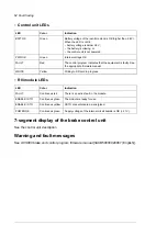
Page 63: ...B connection of the control panel Flickering green There is an active warning in the unit Blinking green There is an active fault in the unit Continuous red There is a fault that requires the stopping and restarting of the drive converter inverter Blinking red The Bluetooth interface is enabled in discoverable mode and ready for pairing Blinking blue ACS AP W only Data is being transferred through...

Page 64: ...nual Red FAULT Writing to SD card in progress Yellow WRITE R8i module LEDs Indication Color LED There is an active fault in the module Continuous red FAULT The module is ready for use Continuous green ENABLE STO XSTO connectors are de energized Continuous yellow ENABLE STO Supply voltage of the internal circuit boards is OK 21 V Continuous green POWER OK 7 segment display of the brake control unit...

Page 65: ...nels Years from start up Maintenance task object 12 11 10 9 8 7 6 5 4 3 2 1 0 Coolant P P P P P P P P P P P P P Checking coolant antifreeze concentration P P P P P P Checking coolant quality R R Coolant draining and replacement I I I I I I I External circuit of the main heat exchanger temperature flow pressure See ACS880 1007LC liquid cooling unit user s manual 3AXD50000129607 English ABB cooling ...

Page 66: ...oolant pipe connections 3AXD10000578918 K 1 To replace the CIO module or reset the fan counters see CIO 01 I O module for distributed I O bus control user s manual 3AXD50000126880 English Symbols Inspection visual inspection and maintenance action if needed I Performance of on off site work commissioning tests measurements or other work P Replacement R Note Maintenance and component replacement in...

Page 67: ...th antistatic hose and nozzle and wear a grounding wristband Using a normal vacuum cleaner creates static discharges which can damage circuit boards 1 Stop the drive and do the steps in section Electrical safety precautions page 35 before you start the work 2 Open the cabinet door 3 Clean the interior of the cabinet Use a vacuum cleaner and a soft brush 4 Clean the air inlets of the fans and air o...

Page 68: ...ake chopper module cubicle WARNING Obey the safety instructions of the drive If you ignore them injury or death or damage to the equipment can occur If you are not a qualified electrical professional do not do installation or maintenance work WARNING Use the required personal protective equipment Wear protective gloves and long sleeves Some parts have sharp edges 1 Repeat the steps described in se...

Page 69: ...Use the required personal protective equipment Wear protective gloves and long sleeves Some parts have sharp edges Note During the fan replacement do not remove the PE busbar on the left side of the cabinet opening 1 Repeat the steps described in section Electrical safety precautions page 35 2 Remove any shrouding in front of the cooling fan 3 Disconnect the fan wiring 4 Undo the four fastening sc...

Page 70: ...tion or maintenance work WARNING Make sure that the replacement module has exactly the same type code as the old module WARNING Beware of hot coolant Do not work on the liquid cooling system until the pressure is lowered down by stopping the pumps and draining the coolant High pressure warm coolant 6 bar max 50 C is present in the internal cooling circuit when it is in operation WARNING Use the re...

Page 71: ...e Use cable ties to keep the wiring out of the way 5 Remove the L shaped DC busbars at the top of the module Make note of the orientation of the screws as well as the order of the washers 6 Close the inlet valve a and outlet valve located on the right hand side of the cubicle Lead the drain hoses b on both sides of the cubicle into a suitable container Open the drain valves c on both sides of the ...

Page 72: ...7 After the module has drained disconnect the piping from the module 72 Maintenance ...

Page 73: ...module carefully out onto a table or other platform Keep the module secured to a hoist or equivalent to prevent the module from falling For information on using the lifting device see Converter module lifting device for drive cabinets hardware manual 3AXD50000210268 English Maintenance 73 ...

Page 74: ...ture have an effect on the life of the capacitors Capacitor life can be extended by decreasing the surrounding air temperature Capacitor failure is usually followed by damage to the unit and an input cable fuse failure or a fault trip If you think that any capacitors in the drive have failed contact ABB Reforming the capacitors The capacitors must be reformed if the drive has not been powered eith...

Page 75: ...bicle Pre tighten the nuts first by hand or by applying a torque of no more than 5 N m 3 7 lbf ft 9 Tighten the nuts to torque as follows Cooper Bussmann fuses 50 N m 37 lbf ft Mersen Ferraz Shawmut 46 N m 34 lbf ft Other Refer to the fuse manufacturer s instructions 1 0 Attach the shrouding if any and close the door Replacing the resistor fuses WARNING Obey the safety instructions given in ACS880...

Page 76: ...the order of the washers on the screws 7 Remove the screws nuts and washers from the old fuses and attach them to the new fuses Make sure to keep the washers in the original order 8 Insert the new fuses into their slots in the cubicle Pre tighten the nuts of the new fuses first by hand or by applying a torque of no more than 5 N m 3 7 lbf ft 9 Tighten the nuts to torque as follows Cooper Bussmann ...

Page 77: ...attery holder has grip nails First slide the battery and then press on the other side The battery will snap in 4 Make sure that the battery polarity shows positive on the upside 5 Put the lid back and tighten it by turning it clockwise 6 Dispose of the old battery according to local disposal rules or applicable laws Memory unit Replacing the memory unit After replacing a control unit you can keep ...

Page 78: ...3 Remove the fastening screw and pull the memory unit out 4 Install a memory unit in reverse order 78 Maintenance ...

Page 79: ...ability The information in this chapter is applicable to cabinet built ACS880 liquid cooled drives Except where otherwise indicated the information is also applicable to drives built out of ACS880 liquid cooled multidrive modules Internal cooling system Each cubicle has an inlet and an outlet manifold fitted with a stop valve and a drain valve The stop valves can be closed to isolate all modules i...

Page 80: ...supply unit each module has a dedicated air to liquid exchanger as shown for item 2 1 Inverter modules 2 To From cooling unit 3 Air to liquid heat exchanger A L Heat sink HS Inlet valve a Inlet side drain valve b Outlet valve c Outlet side drain valve d The coolant used with ACS880 liquid cooled drive systems is Antifrogen L 25 or 50 mixture See Coolant specification page 84 80 Internal cooling ci...

Page 81: ... the limits specified in Technical data page 84 Install a pressure regulator to make sure that the maximum permissible operating pressure is not exceeded Install a bleed valve at the highest point of the cooling circuit and a drain valve at the lowest point The materials that can be used are listed in Cooling circuit materials page 86 Coolant temperature control The temperature of the coolant in t...

Page 82: ... point of the cooling circuit The most practical location for the valve is usually near or at the cooling unit Observe the instructions given by the manufacturer of the cooling unit Pay special attention to filling up and bleeding the pumps properly as they may be damaged if operated when dry Draining coolant into the sewer system is not allowed 1 Open the bleed valve at the cooling unit 2 Open th...

Page 83: ...d valve at the cooling unit 1 4 After one to two minutes stop the pump or block the coolant flow with a valve 1 5 Re check the pressure and add coolant if necessary 1 6 Repeat steps 13 to 15 a few times until all air is let out of the cooling circuit Listen for a humming sound and or feel the piping for vibration to find out if there is still air left in the circuit Internal cooling circuit 83 ...

Page 84: ... circuit with air fill the cooling circuit with coolant specified under Coolant specification page 84 drain the cooling circuit again Maintenance intervals As a general rule the quality of the coolant should be checked at intervals of two years This can be done by distributors of Antifrogen L see www clariant com if a 250 milliliter sample is provided Technical data Coolant specification Coolant t...

Page 85: ...re 0 40 C 32 104 F no drive output current derating required 40 45 C 104 113 F drive output current must be derated by 2 percentage points per 1 C 1 8 F temperature increase as shown by curve a 45 50 C 113 122 F If components with a maximum operating temperature of 55 C 131 F are installed in the same space as the drive modules drive output current must be derated by 6 percentage points per 1 C 1 ...

Page 86: ...ds on heat losses and mass flow Typically 10 C 18 F with nominal losses and flow Pressure limits Base pressure 250 kPa recommended 300 kPa maximum Base pressure denotes the pressure of the system compared with the atmospheric pressure when the cooling circuit is filled with coolant Air counterpressure in expansion vessel with ACS880 1007LC cooling unit 80 kPa Design pressure PS 600 kPa Nominal pre...

Page 87: ...hat are specified above Copper brass or bronze must not be used under any circumstances Even minor dissolution of copper can cause copper precipitation on aluminum and subsequent galvanic corrosion The liquid cooling system must not contain any zinc eg galvanized pipes If the plant incorporates normal iron pipes or cast iron accessories eg motor housings a cooling unit with a heat exchanger such a...

Page 88: ...88 ...

Page 89: ...C A DC A DC kW kVA A DC A DC Ohm Ohm UN 690 V 1110 351 999 370 870 310 781 3 6 3 0 R8i 0870 7 1660 527 1499 555 1300 465 1171 2 4 2 0 R8i 1300 7 2220 702 1998 740 1730 621 1562 3 6 3 0 2 R8i 1730 7 3330 1053 2997 1110 2600 931 2342 2 4 2 0 2 R8i 2600 7 4990 1580 4496 1665 3900 1396 3514 2 4 2 0 3 R8i 3900 7 6650 2106 5994 2220 5200 1862 4685 2 4 2 0 4 R8i 5200 7 8320 2633 7493 2775 6500 2327 5856 ...

Page 90: ...ule Rmin Maximum resistance value of the brake resistor per one phase of the brake module Rmax Connect one resistor per brake chopper module phase For example a brake unit of frame size 2 R8i includes two brake chopper modules 2 3 resistors are needed Note No overload use Input current Input current with Rmin is given in the type designation label I1 Output current This is indicated in the type de...

Page 91: ...019 3040 3720 5208 3633 4252 3466 3571 3328 2976 2773 3AXD00000601909 XLS Nominal ratings UN Nominal input voltage For U1 see Electrical power network specification on page 139 For U2 see DC connection data on page 139 I1 Continuous rms input AC current No overload capability at the coolant temperature of 40 C 104 F and air temperature of 45 C 113 F I2 Continuous rms output DC current No overload ...

Page 92: ...04LC 0530A 7 1 R8i 0870 7 ACS880 104LC 0850A 7 1 R8i 1300 7 ACS880 104LC 0530A 7 2 2 R8i 1730 7 ACS880 104LC 0850A 7 2 2 R8i 2600 7 ACS880 104LC 0850A 7 3 3 R8i 3900 7 ACS880 104LC 0850A 7 4 4 R8i 5200 7 ACS880 104LC 0850A 7 5 5 R8i 6500 7 Fuses DC fuses IEC IEC ACS880 607LC Qty total Qty per module Data Type UN 690 V 2 2 1250 A 1250 V 170M6500 0870 7 2 2 2 2 2 1000 A 1100 V 2 x 170M6548 1300 7 4 ...

Page 93: ... 170M6546 3900 7 12 1 800 A 1250 V 170M6546 5200 7 15 1 800 A 1250 V 170M6546 6500 7 Dimensions weights and free space requirements Weight4 Weight3 Depth Width2 Width1 Space above Height2 Height1 ACS880 607LC kg kg mm mm mm mm mm mm UN 690 V 610 370 644 700 400 250 2056 2002 0870 7 610 370 644 700 400 250 2056 2002 1300 7 1220 740 644 1400 800 250 2056 2002 1730 7 1220 740 644 1400 800 250 2056 20...

Page 94: ...1 5 5 6 0 8 3 2 1730 7 66 120 10 1 8 5 32 1 5 5 6 0 8 3 2 2600 7 68 120 15 1 12 7 48 2 2 8 4 1 3 4 8 3900 7 69 120 20 1 16 9 64 3 0 11 2 1 7 6 4 5200 7 70 120 25 2 21 1 80 3 7 14 0 2 1 8 0 6500 7 Terminal and cable entry data for the resistor cables These drawings show the terminal and cable entry dimensions for the resistor cables The dimensions are given in millimeters Tightening torques depend ...

Page 95: ... Bottom entry and exit of cables Dimensions in mm 1 mm 0 0394 in Technical data 95 ...

Page 96: ...Dimensions in mm 1 mm 0 0394 in 96 Technical data ...

Page 97: ... Top entry and exit of cables Dimensions in mm 1 mm 0 0394 in Technical data 97 ...

Page 98: ...ss Max torque Size 8 8 5 N m 44 lbf in M6 8 8 9 N m 6 6 lbf ft M8 8 8 18 N m 13 3 lbf ft M10 8 8 31 N m 23 lbf ft M12 Cable lugs Strength class Max torque Size 8 8 15 N m 11 lbf ft M8 8 8 32 N m 23 5 lbf ft M10 8 8 50 N m 37 lbf ft M12 Typical resistor cable sizes This table gives copper cable types Cable sizing is based on max 9 cables laid on a cable ladder side by side three ladder type trays o...

Page 99: ...nd stress on chopper IGBTs The longer the cable the higher the EMC emissions The longer the cable the higher the inductive load and voltage peaks over the IGBT semiconductors of the brake chopper Resistor connection 0 U1 3 phase symmetrical Voltage U2 For ACS880 104LC xxxx 7 modules This is indicated in the type designation label as typical output voltage levels 3 0 742 849 976 V DC 300 m 984 ft M...

Page 100: ... contact ABB Installation site altitude Output derated above 1000 m 3281 ft 40 to 70 C 40 to 158 F 40 to 70 C 40 to 158 F 0 45 C 32 113 F no con densation allowed Output derated in the range 45 55 C 113 131 F Air temperature Max 95 Max 95 Max 95 Relative humidity No condensation allowed Maximum allowed relative humidity is 60 in the presence of corrosive gases IEC 60721 3 2 1997 IEC 60721 3 1 1997...

Page 101: ...t the top to the package walls against swaying inside the package Package elements are attached to each other with screws Timber polyethylene sheet thickness 0 15 mm stretch film thickness 0 023 mm PP tape PET strap sheet metal steel Standard package For land and air transport when planned storage time is less than 2 months or when storage can be arranged in clean and dry conditions less than 6 mo...

Page 102: ...ing 3AXD50000048634 English Disclaimers Generic disclaimer The manufacturer shall have no obligation with respect to any product which i has been improperly repaired or altered ii has been subjected to misuse negligence or accident iii has been used in a manner contrary to the manufacturer s instructions or iv has failed as a result of ordinary wear and tear Cybersecurity disclaimer This product i...

Page 103: ...Dimension drawings Contents of this chapter This chapter contains dimension drawings for the brake unit 13 Dimension drawings 103 ...

Page 104: ...Brake unit with bottom exit Dimensions in mm 1 mm 0 0394 in 104 Dimension drawings ...

Page 105: ...Brake unit with top exit Dimensions in mm 1 mm 0 0394 in Dimension drawings 105 ...

Page 106: ...Bottom Top Dimensions in mm 1 mm 0 0394 in 106 Dimension drawings ...

Page 107: ...e contacts can be found by navigating to www abb com searchchannels Product training For information on ABB product training navigate to new abb com service training Providing feedback on ABB manuals Your comments on our manuals are welcome Navigate to new abb com drives manuals feedback form Document library on the Internet You can find manuals and other product documents in PDF format on the Int...

Page 108: ...www abb com drives 3AXD50000581627A Copyright 2020 ABB All rights reserved Specifications subject to change without notice 3AXD50000581627 Rev A EN EFFECTIVE 2020 10 02 ...

Reviews: