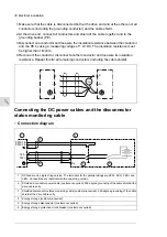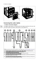
Indicator lamp on cabinet door: Energy storage disconnector is disconnected. See no. 10.
P12.1
Cooling fan status indication. Energized: Fan in operation. Optional user-connection is not shown.
1
Unit with DC switch disconnector ([Q11], F290): Q11.1 status indication. Open contact: Q11.1
is open. Optional user-connection is not shown.
2
Unit with DC switch disconnector ([Q11], F290): Q11.1 status indication. Closed: Q11.1 is open.
Optional user-connection is not shown.
3
Unit with DC switch disconnector ([Q11], F290): Q11.1 interlocking. Obligatory user-connection
(no. 5) is shown with dashed line. When de-energized, the interlocking prevents accidental closure of
the DC switch disconnector.
4
Unit with DC switch disconnector ([Q11.1], F290): External power supply for the interlocking
circuit (no. 4), 24 V / 7W. Obligatory user-connection is shown with dashed line. De-energized: Interlocking
is active. Closure of Q11 is not possible. Energized: Interlocking is inactive.
5
Circuit for the DC feeder disconnected indication. Internal connections.
6
Supply for circuit no. 6 and 8. Internal connection.
7
Circuit for energy storage disconnected indication.
8
Energy storage disconnector monitoring. Obligatory user-connection is shown with dashed line.
9
Unit equipped with charging switch ([Q10], F272): Q10 status indication. Open contact: Q10 is
open. Optional user-connection is not shown.
10
Unit equipped with charging switch ([Q10], F272): Q10 status indication. Closed contact: Q10
is open. Optional user-connection is not shown.
11
Unit equipped with a common mode filter ([R11.11, R11.12, F45], E208): Overtemperature in-
dication of filter. Optional user-connection is not shown in the diagram.
12
■
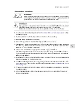
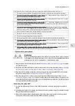
Connection procedure
WARNING!
Obey the safety instructions of the drive. If you ignore them, injury or death,
or damage to the equipment can occur. If you are not a qualified electrical
professional, do not do installation or maintenance work.
1. Stop the drive and do the steps in section
Electrical safety precautions (page 27)
before
you start the work.
2. Open the door of the DC/DC converter cubicle and remove the shrouding. See
the DC power cables and the disconnector status monitoring cable (page 30)
.
3. Run the control cables inside the cubicle. Ground the cable shields 360° at the cable
entry. See subsection
Grounding the cable 360° (page 33)
.
4. Run the cables to the control connections terminal X350 and connect. See
. Leave enough slack to the cables where necessary. The
terminal block for the user connections is on a hinged swing-out frame. The frame needs
to be opened for maintenance work.
Grounding the cable 360°
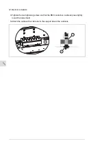
1. Loosen the tightening screws of the EMI conductive cushions and pull the cushions
apart.
2. Cut adequate holes to the rubber grommets in the entry plate and put the cables through
the grommets and the cushions.
3. Strip off the cable plastic sheath above the entry plate just enough to ensure proper
connection of the bare shield and the EMI conductive cushions.
Electrical installation 33
11
Summary of Contents for ACS880-7107LC DC
Page 1: ... ABB INDUSTRIAL DRIVES ACS880 7107LC DC feeder unit Hardware manual ...
Page 2: ......
Page 4: ......
Page 8: ...8 ...
Page 12: ...12 ...
Page 22: ...22 ...
Page 36: ...36 ...
Page 40: ...40 ...
Page 44: ...44 ...
Page 50: ...50 ...
Page 52: ...52 ...
Page 55: ...Terminal and cable entry data for the power cables Technical data 55 ...

