background image

• Cut the shield at the midpoint of the bare part. Be careful not to cut the conductors or the

grounding wire (if present).

• Turn the shield inside out to expose its conductive surface.

• Cover the turned shield and the stripped cable with copper foil to keep the shielding

continuous.

1

A

B

C

2

2

3
4

5

Stripped cable

A

Conductive surface of the shield exposed

B

Stripped part covered with copper foil

C

Cable shield

1

Copper foil

2

Shielded twisted pair

3

Grounding wire

4

Note for top entry of cables:

When each cable has its own rubber grommet, sufficient IP

and EMC protection can be achieved. However, if there is more than one cable per grommet,
plan the installation beforehand as follows:

1. Make a list of the cables coming to the cabinet.

2. Sort the cables going to the left into one group and the cables going to the right into

another group to avoid unnecessary crossing of cables inside the cabinet.

3. Sort the cables in each group according to size.

4. Group the cables for each grommet as follows ensuring that each cable has a proper

contact to the cushions on both sides.

Max. number of cables per grommet

Cable diameter in mm

4

≤ 13

3

≤ 17

2

< 25

1

≥ 25

5. Arrange the bunches according to size from thickest to the thinnest between the EMI

conductive cushions.

Electrical installation 37

11

Summary of Contents for ACS880-7207LC

Page 1: ... ABB INDUSTRIAL DRIVES ACS880 7207LC and 7307LC DC incoming units Hardware manual ...

Page 2: ......

Page 3: ...ACS880 7207LC and 7307LC DC incoming units Hardware manual Table of contents 4 Electrical installation 6 Start up 3AXD50000752430 Rev A EN Original instructions EFFECTIVE 2021 10 01 ...

Page 4: ......

Page 5: ... with a DC incoming unit 18 Layout of a DC incoming unit 19 Control of the DC incoming unit 20 Type designation label 21 Type designation key 21 Basic code 21 Option codes 3 Guidelines for planning the electrical installation 23 Contents of this chapter 23 Limitation of liability 23 Generic guidelines 24 Selecting and routing the DC cables 24 Recommended cables 24 Typical cable sizes types 24 Mini...

Page 6: ...s of this chapter 6 Start up 41 Contents of this chapter 41 Start up procedure 7 Operating instructions 45 Contents of this chapter 45 Opening the DC isolator breaker Q340 46 Closing the DC isolator breaker Q340 47 Isolating disconnecting the DC isolator breaker Q340 48 De isolating the DC isolator breaker Q340 8 Fault tracing 49 Contents of this chapter 49 Indicators on the cabinet door 9 Mainten...

Page 7: ...0 Control cable terminal data 60 Auxiliary circuit current consumption 60 Energy efficiency data ecodesign 60 Protection classes 60 Ambient conditions 61 Materials 61 Color 62 Package 62 Disposal 62 Applicable standards 62 Markings 62 Disclaimers 62 Generic disclaimer 63 Cybersecurity disclaimer Further information Table of contents 7 ...

Page 8: ...8 ...

Page 9: ...n specific warnings and notes before changing the default settings of a function For each function the warnings and notes are given in the section describing the related user adjustable parameters Read the task specific safety instructions before starting the task See the section describing the task Target audience This manual is intended for people who plan the installation install start up and d...

Page 10: ...ted manuals Related drive manuals Code Manual General manuals 3AXD50000048633 ACS880 liquid cooled multidrive cabinets and modules safety instructions 3AXD50000048634 ACS880 liquid cooled multidrive cabinets and modules electrical planning instructions 3AXD50000048635 ACS880 liquid cooled multidrive cabinets mechanical installation instructions 3AXD50000126880 CIO 01 I O module for distributed I O...

Page 11: ... tool user s manual 3AXD50000210268 Converter module lifting device for drive cabinets hardware manual Manuals for I O extension modules fieldbus adapters safety options etc You can find manuals on the Internet See www abb com drives documents For manuals not available in the document library contact your local ABB representative Related DC isolator breaker and protection relay manuals SACE Emax D...

Page 12: ...12 ...

Page 13: ...ents of this chapter This chapter describes the intended use and construction of DC incoming units ACS880 7207LC and ACS880 7307LC The chapter also presents the type designation label and the type code 2 Operation principle and hardware description 13 ...

Page 14: ...the two DC systems and make and break load currents It can also break fault currents at certain extent ACS880 7307LC can only isolate disconnect the two DC systems It cannot make or break load current or break fault current The main component both in the ACS880 7207LC and ACS880 7307LC units is a DC isolator breaker The size and the connection of the DC isolator breaker vary depending on it s inte...

Page 15: ... switch disconnector 2 Supply module 3 DC bus 4 Inverter modules 5 Motor s acquired by user 6 Withdrawable DC isolator breaker 7 ACS880 7207LC Isolator disconnector and breaker Q340 ACS880 7307LC Isolator disconnector Q340 For ACS880 7307LC the generator circuit must also be equipped with a separate breaker It is not visible in the drawing above AC DC rectifier 8 External generator acquired by use...

Page 16: ...ncoming unit E AC supply 1 Main breaker or main contactor and main switch disconnector 2 Supply module 3 DC bus 4 Inverter modules 5 Motor s acquired by user 6 Withdrawable DC isolator breaker 7 ACS880 7207LC Isolator disconnector and breaker Q340 ACS880 7307LC Isolator disconnector Q340 Semiconductor switch unit ACS880 7407LC 8 16 Operation principle and hardware description ...

Page 17: ...Layout drawings Layout of a drive system with a DC incoming unit 1 2 3 4 Supply unit 1 and 2 DC incoming unit ACS880 7207LC 3 Inverter unit 4 Operation principle and hardware description 17 ...

Page 18: ...erminals 1DC 1DC option G316 4 DC isolator breaker Q340 5 Terminal block for the DC isolator breaker control connections X340 6 Terminal block for earth fault monitoring relay X90 option Q987 7 Cooling inlet manifold with stop and drain valves 8 Heat exchanger 9 Fan G115 10 Cooling outlet manifold with stop and drain valves 11 18 Operation principle and hardware description ...

Page 19: ...wo illuminated push buttons S90 1 and S90 2 for earth fault monitoring relay A90 1 and A90 2 option Q987 or 2Q987 LED on Alarm 2 One or two voltage meters P92 x option G352 or 2G352 3 ACS880 7207LC only Protection relay 4 Feeder protection REF615 A980 Generator connection option Q988 REG615 A980 Operation principle and hardware description 19 ...

Page 20: ...nd other additional data 3 Degree of protection 4 Ratings 5 Valid markings See ACS880 liquid cooled multidrive cabinets and modules electrical planning instruc tions 3AXD50000048634 English 6 Serial number The first digit of the serial number refers to the manufacturing plant The next four digits refer to the unit s manufacturing year and week respectively The remaining digits complete the serial ...

Page 21: ... codes The table below lists the option codes Description Code 50 Hz supply frequency A012 60 Hz supply frequency A013 IP42 UL Type 1 Filtered B054 IP54 UL Type 12 B055 Marine construction C121 Plinth height 100 mm C164 Door hinges on left C176 Plinth height 200 mm C179 Marine product certification issued by DNV GL C205 Marine product certification issued by the American Bureau of Shipping ABS C20...

Page 22: ... voltmeter G352 Current transducers G353 Power cabling exit from bottom H352 Power cabling exit from top H353 Cable gland plates 3 mm steel undrilled H358 Cable gland plates 3 mm aluminum undrilled H364 Cable gland plates 6 mm brass undrilled H365 Control cabling through floor of cabinet H367 Control cabling through roof of cabinet H368 Cable entry 72 mm diameter H390 Cable entry Roxtec frame with...

Page 23: ... whatsoever for any installation which breaches the local laws and or other regulations Furthermore if the recommendations given by ABB are not followed the drive may experience problems that the warranty does not cover Generic guidelines See ACS880 liquid cooled multidrive cabinets and modules electrical planning instructions 3AXD50000048634 English for the generic guidelines for planning the ele...

Page 24: ...or must obey these rules in order to minimize the electromagnetic interference caused by rapid current changes in the DC cables Shield the cabling completely either by using shielded cable or a metallic enclosure Unshielded single core cable can only be used if it is routed inside a cabinet that efficiently suppresses radiated emissions Install the cables away from other cable routes Avoid long pa...

Page 25: ...is chapter contains electrical safety precautions instructions for measuring the insulation of the external power cabling connection diagrams and instructions for connecting the external power cabling and control cabling 4 Electrical installation 25 11 ...

Page 26: ...nnector if present and all other possible disconnecting devices that isolate the drive from dangerous voltage sources In the liquid cooling unit if present open the switch disconnector of the cooling pumps If you have a permanent magnet motor connected to the drive disconnect the motor from the drive with a safety switch or by other means Disconnect all dangerous external voltages from the control...

Page 27: ...DC and UDC and the grounding PE terminal is zero In cabinet built drives measure between the drive DC busbars and and the grounding PE busbar WARNING The busbars inside the cabinet of liquid cooled drives are partially coated Measurements made through the coating are potentially unreliable so only measure at uncoated portions Note that the coating does not constitute a safe or touch proof insulati...

Page 28: ...uits inside the drive which cut down the testing voltage automatically Check the DC cabling as follows 1 Make sure that the cable is disconnected both at the drive end and at the other end all conductors including the grounding conductor and the cable shield 2 At the drive end connect all conductors and shield of the cable together and to the grounding busbar PE 3 Disconnect one conductor and meas...

Page 29: ...gram 1DC 1DC 1 2 4 3 DC incoming unit with single DC terminals Large units have parallel terminals 2DC and 2DC in addition 1 Shielded 4 conductor power cable customer acquired 2 Generator and AC DC converter assembly the external DC power supply 3 Cable shield and protective earth conductor 360 degree grounding at the drive cable entry 4 Electrical installation 29 11 ...

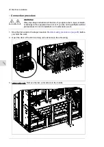
Page 30: ...u are not a qualified electrical professional do not do installation or maintenance work 1 Stop the drive and do the steps in section Electrical safety precautions page 26 before you start the work 2 Open the door of the DC incoming unit and remove the shrouding 3 Large units only Remove the two vertical bars in the middle 30 Electrical installation ...

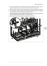
Page 31: ...uded in the delivery 6 Connect the DC and DC conductors to DC terminals with cable lugs b Use the bolts nuts and washers included in the delivery Tighten to 70 N m 7 Twist the cable shields into bundles and connect them with the cable lugs to the protective grounding busbars PE of the cabinet c Tighten to 42 N m 8 Install the bars and shrouding removed earlier and close the door 1DC 1DC 2DC 2DC c ...

Page 32: ...move the rubber grommets from the cable entries for the cables to be connected Cut adequate holes into the rubber grommets The holes must be tight for proper sealing Slide the grommets onto the cables 2 Slide the cables into the cubicle through the conductive sleeves and attach the grommets to the holes 3 Strip the outer sheath of the cable and attach the conductive sleeve to the bare shield with ...

Page 33: ...ng When the control circuit energizes the YC coil rising edge of the signal the DC isolator breaker Q340 closes Opening When the control circuit energizes the YO coil rising edge of the signal the DC isolator breaker Q340 opens The DC isolator breaker Q340 can be closed only when the YU coil is energized level signal Closing is mechanically locked If the YU coil is not energized the YO and YC coil...

Page 34: ...e main contacts are closed 2 Cranked in status indication Auxiliary contact is closed when the withdrawable DC isolator breaker is cranked in 3 Test status indication Auxiliary contact is closed when the withdrawable DC isolator breaker is in test position main contacts still isolated disconnected but auxiliary signals connected 4 User connections and user defined monitoring circuit dashed lines T...

Page 35: ...ed when the monitoring relay is energized For a two relay system option 2Q987 the alarm of the second relay is connected to X90 15 16 1 Insulation level alarm 1 For a two relay system option 2Q987 the alarm 1 of the second relay is connected to X90 17 18 2 Insulation level alarm 2 For a two relay system option 2Q987 the alarm 2 of the second relay is connected to X90 19 20 3 User connections and u...

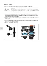
Page 36: ...very specific circuit diagrams Grounding the outer shields of the control cables at the cabinet entry Ground the outer shields of all control cables 360 degrees at the EMI conductive cushions as follows example constructions are shown below the actual hardware may vary 1 Loosen the tightening screws of the EMI conductive cushions and pull the cushions apart 2 Cut adequate holes to the rubber gromm...

Page 37: ...ufficient IP and EMC protection can be achieved However if there is more than one cable per grommet plan the installation beforehand as follows 1 Make a list of the cables coming to the cabinet 2 Sort the cables going to the left into one group and the cables going to the right into another group to avoid unnecessary crossing of cables inside the cabinet 3 Sort the cables in each group according t...

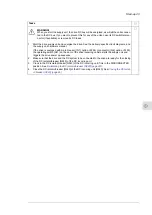
Page 38: ...the conductors to the appropriate terminals see page 127 of the control unit or terminal block X504 option L504 Connect the inner twisted pair shields and all separate grounding wires to the grounding clamps below the control unit The drawing below represents a drive with additional I O terminal block option L504 Without the block the grounding is made the same way Notes Do not ground the outer sh...

Page 39: ... DC cabling if any has been connected to the correct terminals and the terminals have been tightened to the torque specified If external DC power cables are connected to DC incoming unit There is an adequately sized protective earth ground conductor between the external DC system and the drive the conductor has been connected to the appropriate terminal and the terminal has been tightened to the t...

Page 40: ...40 ...

Page 41: ... that means no voltage is or cannot be connected to drive inadvertently Make sure that all external auxiliary circuits are switched off and disconnected See the start up instruc tions in the supply unit hardware manual Make sure that the supply unit is switched off and the drive system has been isolated from the supply network Make sure that the DC switch disconnectors Q11 in inverter units and ot...

Page 42: ...t is safe to start the work Do the steps in section Electrical safety precautions page 26 Starting and checking the cooling system Fill up and bleed the internal cooling circuit Start the cooling unit up See ACS880 107LC inverter units hardware manual 3AXD50000196111 English and ACS880 1007LC liquid cooling unit user s manual 3AXD50000129607 English Check the cooling system for leaks Make sure tha...

Page 43: ...r Q1 option F255 or contactor Q2 option F250 the operating switch S21 on the door of the drive incoming cubicle starts the supply unit and triggers the drive power up sequence 2 Make sure that the drive and the DC system to be connected to the drive are ready for the closing of the DC isolator breaker Q340 of the DC incoming unit 3 Crank in the DC isolator breaker Q340 of the DC incoming unit if i...

Page 44: ...44 ...

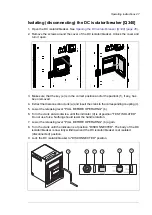
Page 45: ...ation not for connection or disconnection the load current Make sure that the necessary interlocking control connections have been implemented on site to prevent these operations WARNING Do not open or close the DC isolator breaker with the control buttons on the front panel of the breaker There is a protective cover in front of the buttons to prevent the use Do not remove it To open the breaker e...

Page 46: ...control buttons on the front panel of the breaker There is a protective cover in front of the buttons to prevent the use Do not remove it To close the breaker 1 Make sure that it is safe to close the DC isolator breaker 2 If the DC isolator breaker is in isolated disconnected position de isolate it That is crank in the withdrawn DC isolator breaker See De isolating the DC isolator breaker Q340 pag...

Page 47: ... the crank to the corresponding coupling c 5 Lower the releasing lever PULL BEFORE OPERATING b 6 Turn the crank anti clockwise until the indicator d is at position TEST ISOLATED Do not use force Nothing should resist the handle rotation 7 Lower the releasing lever PULL BEFORE OPERATING b again 8 Turn the crank until the indicator is at position DISCONNECTED The body of the DC isolator breaker is n...

Page 48: ...c 4 Lower the releasing lever PULL BEFORE OPERATING b 5 Turn the crank clockwise until the indicator d is at position TEST ISOLATED Do not use force Nothing should resist the handle rotation 6 Lower the releasing lever PULL BEFORE OPERATING b again 7 Turn the crank until the indicator is at position CONNECTED The body of the DC isolator breaker is now cranked in that means the breaker is in the de...

Page 49: ... The button remains illuminated until the relay does not detect the cause for the alarm anymore and the user resets the alarm indication by pushing the button EARTH FAULT ALARM1 S90 1 Earth fault detected by the earth fault monitoring relay 2 A90 2 option 2Q987 The relay monitors the earth fault in between the DC isolator breaker and the external DC system The button illuminates when the relay det...

Page 50: ...50 ...

Page 51: ...ow the maintenance tasks which can be done by the end user The complete maintenance schedule is available on the Internet www abb com drivesservices For more information consult your local ABB Service representative www abb com searchchannels Description of symbols Description Action Inspection visual inspection and maintenance action if needed I Performance of on off site work commissioning tests...

Page 52: ...oolant draining and refill Cabinet fans and fan control board R R Cooling fans 230 VAC 50 60Hz R R R Cooling fans 115 VAC 50 60Hz Aging R Cabinet auxiliary power supplies Note Maintenance and component replacement intervals are based on the assumption that the equipment is operated within the specified ratings and ambient conditions ABB recommends annual drive inspections to ensure the highest rel...

Page 53: ...cleaning cloth Moisten with clean water or mild detergent pH 5 9 for metal pH 5 7 for plastic WARNING Prevent water from entering the drive Never use excessive amount of water a hose steam etc Power connections Retightening the power connections WARNING Obey the safety instructions of the drive If you ignore them injury or death or damage to the equipment can occur If you are not a qualified elect...

Page 54: ...nance work 1 Stop the drive and do the steps in section Electrical safety precautions page 26 before you start the work 2 Disconnect the fan wiring a 3 Large units with parallel fans Remove the vertical bar or bars b in the middle 4 Undo the two screws that attach the fan housing to the cabinet frame and pull the fan housing out The number of fans depends on the size of the unit 5 Install the new ...

Page 55: ...Internal cooling circuit See ACS880 107LC inverter units hardware manual 3AXD50000196111 English 10 Internal cooling circuit 55 ...

Page 56: ...56 ...

Page 57: ...0 1050 7 976 1171 1200 DICU6 1200A 7 25 25 80 1050 7 976 1366 1400 DICU6 1400A 7 25 25 80 1050 7 976 1562 1600 DICU6 1600A 7 40 40 180 1050 7 976 2147 2200 DICU7 2200A 7 40 40 180 1050 7 976 2342 2400 DICU7 2400A 7 65 65 143 1050 7 976 2733 2800 DICU10 2800A 7 65 65 143 1050 7 976 3026 3100 DICU10 3100A 7 65 65 200 1050 7 976 3709 3800 DICU12 3800A 7 65 65 200 1050 7 976 4294 4400 DICU12 4400A 7 6...

Page 58: ...rent power Sn nominal DC supply voltage Un peak short circuit current Ip ultimate breaking capacity Icu short circuit withstand capacity Icw Dimensions and weights Weight Depth Width Height ACS880 7207LC kg mm mm mm 415 737 600 2013 1200A 7 415 737 600 2013 1400A 7 415 737 600 2013 1600A 7 460 737 700 2013 2200A 7 460 737 700 2013 2400A 7 758 737 1000 2013 2800A 7 785 737 1000 2013 3100A 7 1005 73...

Page 59: ...9 0 03 1 22 1 25 2200A 7 120 8 3 9 0 04 1 40 1 44 2400A 7 120 16 5 8 0 03 1 33 1 36 2800A 7 120 16 5 8 0 04 1 57 1 62 3100A 7 120 24 7 5 0 04 1 50 1 54 3800A 7 120 24 7 5 0 06 2 16 2 22 4400A 7 120 24 7 5 0 06 2 42 2 49 5000A 7 Liquid quantity Losses ACS880 7307LC Pressure loss Massflow Total Ploss air Ploss coolant Ploss total kPa l l kW kW kW 120 8 3 4 0 02 0 61 0 62 2000A 7 120 8 3 4 0 02 0 77 ...

Page 60: ...iency data is not provided for the drive unit The multidrives are not in the scope of the EU ecodesign requirements Regulation EU 2019 1781 or the UK ecodesign requirements Regulation SI 2021 No 745 Protection classes IP42 standard IP54 option B055 Degrees of protection IEC EN 60529 UL Type 1 standard UL Type 12 option B055 For indoor use only Enclosure types UL50 III except for auxiliary power co...

Page 61: ...king must support this otherwise 1S2 Chemical gases Class 3C2 Solid particles Class 3S2 No conductive dust al lowed 2 Pollution degree IEC EN 60721 3 2 1997 IEC EN 60721 3 1 1997 IEC EN 60721 3 3 2002 Vibration 2 9 Hz max 3 5 mm amplitude 10 57 Hz max 0 075 mm amplitude 10 57 Hz max 0 075 mm amplitude IEC EN 61800 5 1 IEC 60068 2 6 2007 EN 60068 2 6 2008 Envir onmental testing Part 2 Tests Test Fc...

Page 62: ...ecycled as material Plastics rubber cardboard and other packaging material can be used in energy recovery Printed circuit boards and large electrolytic capacitors need selective treatment according to IEC 62635 guidelines To aid recycling plastic parts are marked with an appropriate identification code Contact your local ABB distributor for further information on environmental aspects and recyclin...

Page 63: ... establish and maintain any appropriate measures such as but not limited to the installation of firewalls prevention of physical access application of authentication measures encryption of data installation of anti virus programs etc to protect the product the network its system and the interface against any kind of security breaches unauthorized access interference intrusion leakage and or theft ...

Page 64: ...64 ...

Page 65: ... by navigating to www abb com searchchannels Product training For information on ABB product training navigate to new abb com service training Providing feedback on ABB manuals Your comments on our manuals are welcome Navigate to new abb com drives manuals feedback form Document library on the Internet You can find manuals and other product documents in PDF format on the Internet at www abb com dr...

Page 66: ...www abb com drives 3AXD50000752430A Copyright 2021 ABB All rights reserved Specifications subject to change without notice 3AXD50000752430 Rev A EN EFFECTIVE 2021 10 01 ...

Reviews: