Parameters 347
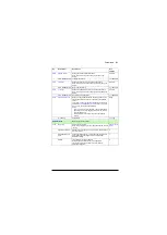
Number of full minutes passed since midnight. For
example, the value 860 corresponds to 2:20 pm.
See parameter
0 min
1…1439
Minutes since midnight.
1 = 1
Number of milliseconds passed since last minute.
See parameter
0 ms
0…59999
Number of milliseconds since last minute.
1 = 1
Time source status word.
This parameter is read-only.
-
0000h…FFFFh
Time source status word 1.
1 = 1
Specifies an ID number for the drive. The ID can be read
by an external controller through DDCS, for example, for
comparison with an ID contained by the controller’s
application.
0
0...32767
Drive ID number
1 = 1
No.
Name/Value
Description
Def/
FbEq16
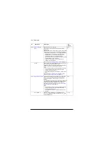
Bit
Name
Description
0
Time tick received
1 = 1st priority tick received: Tick has been received from 1st
priority source.
1
Aux Time tick
received
1 = 2nd priority tick received: Tick has been received from 2nd
priority source.
2
Tick interval is too
long
1 = Yes: Tick interval too long (accuracy compromised).
3
DDCS controller
1 = Tick received: Tick has been received from an external
controller.
4
Master/Follower
1 = Tick received: Tick has been received through the
master/follower link.
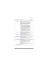
5
Reserved
6
D2D
1 = Tick received: Tick has been received through the drive-to-
drive link.
7
FbusA
1 = Tick received: Tick has been received through fieldbus
interface A.
8
FbusB
1 = Tick received: Tick has been received through fieldbus
interface B.
9
EFB
1 = Tick received: Tick has been received through the embedded
fieldbus interface.
10
Ethernet
1 = Tick received: Tick has been received through the Ethernet
port on type BCU control unit.
11
Panel link
1 = Tick received: Tick has been received from the control panel,
or Drive composer PC tool connected to the control panel.
12
Ethernet tool link
1 = Tick received: Tick has been received from Drive composer
PC tool through an FENA module.
13
Parameter setting
1 = Tick received: Tick has been set by parameters
.
14
RTC
1 = RTC time in use: Time and date have been read from the
real-time clock.
15
Drive On-Time
1 = Drive on-time in use: Time and date are displaying drive on-
time.
Summary of Contents for ACS880 PCP
Page 1: ...ABB industrial drives Firmware manual ACS880 PCP ESP control program ...
Page 4: ......
Page 28: ...28 PCP ESP control start up ...
Page 30: ...30 Using the control panel ...
Page 94: ...94 Standard programposi features ...
Page 100: ...100 Default control connections ...
Page 360: ...360 Parameters ...
Page 436: ...436 Fault tracing ...
Page 486: ...486 Control chain diagrams ...
Page 492: ...492 Appendix ESP with step up transformer and sine filter ...
Page 494: ...Contact us www abb com drives www abb com drivespartners 3AXD50000016186 Rev B EN 2015 10 27 ...


