Fault tracing
199
Fault tracing
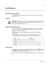
What this chapter contains
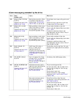
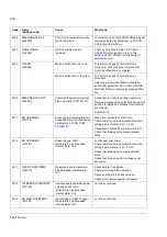
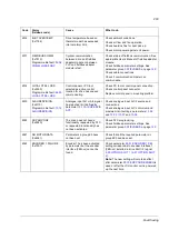
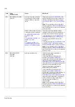
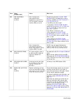
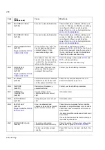
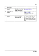
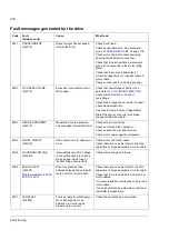
The chapter lists all alarm and fault messages including the possible cause and
corrective actions.
Safety
WARNING!
Only qualified electricians are allowed to maintain the drive. The
Safety
Instructions
on the first pages of the appropriate hardware manual must be read
before you start working with the drive.
Alarm and fault indications
An alarm or a fault message indicates abnormal drive status. Most alarm and fault
causes can be identified and corrected using this information. If not, an ABB
representative should be contacted.
The four-digit code number in brackets after the message is for the fieldbus
communication.
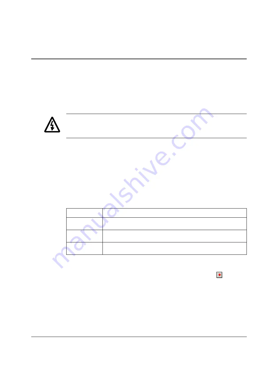
The alarm/fault code is displayed on the 7-segment display of the drive. The
following table describes the indications given by the 7-segment display.
How to reset
The drive can be reset either by pressing the reset key on the PC tool (
) or control
panel (
RESET
) or switching the supply voltage off for a while. When the fault has
been removed, the motor can be restarted.
A fault can also be reset from an external source by parameter
.
Display
Meaning
“E-” followed by
error code
System error. See appropriate drive hardware manual.
“A-” followed by
error code
Alarm. See section
Alarm messages generated by the drive
on page
.
“F-” followed by
error code
Fault. See section
Fault messages generated by the drive
.
Summary of Contents for ACSM1 Series
Page 1: ...ACSM1 Firmware Manual ACSM1 Speed and Torque Control Program...
Page 2: ......
Page 4: ......
Page 12: ...Table of contents 12...
Page 49: ...Drive control and features 49...
Page 282: ...Standard function blocks 282...
Page 306: ...Application program template 306...
Page 312: ...Control chain block diagrams 312...
Page 331: ...331...
Page 332: ...332...
Page 333: ......

