Standard function blocks
233
Communication
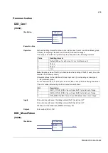
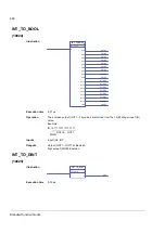
D2D_Conf
(10092)
Illustration
Execution time
-
Operation
Defines handling interval for drive-to-drive references 1 and 2, and the address (group
number) for outgoing standard (non-chained) multicast messages.
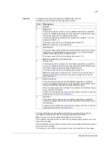
The values of the Ref1/2 Cycle Sel inputs correspond to the following intervals:
Note:
Negative value of Ref2 Cycle Sel disables the handling of Ref2 (if used, it must be
disabled in all follower drives).
Allowable values for the Std Mcast Group input are 0 (= multicasting not used) and
1…62 (multicast group).
An unconnected input, or an input in an error state, is interpreted as having the value 0.
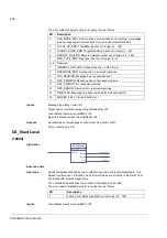
The error codes indicated by the Error output are as follows:
Inputs
Drive-to-drive reference 1 handling interval (Ref1 Cycle Sel): INT
Drive-to-drive reference 2 handling interval (Ref2 Cycle Sel): INT
Standard multicast address (Std Mcast Group): INT
Outputs
Error output (Error): PB
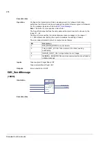
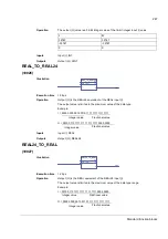
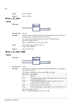
D2D_McastToken
(10096)
Illustration
D2D_Conf
70
TLA1 1 msec
(1)
Ref1 Cycle Sel
Ref2 Cycle Sel
Std M cast Group
Error
Error(70)
Value
Handling interval
0
Default (500 µs for reference 1; 2 ms for reference 2)
1
250 µs
2
500 µs
3
2 ms
Bit
Description
0
REF1_CYCLE_ERR: Value of input Ref1 Cycle Sel out of range
1
REF2_CYCLE_ERR: Value of input Ref2 Cycle Sel out of range
2
STD_MCAST_ERR: Value of input Std Mcast Group out of range
D2D_McastToken
71
TLA1 1 msec
(1)
Target Node
Mcast Cycle
Error
Error(71)
Summary of Contents for ACSM1 Series
Page 1: ...ACSM1 Firmware Manual ACSM1 Speed and Torque Control Program...
Page 2: ......
Page 4: ......
Page 12: ...Table of contents 12...
Page 49: ...Drive control and features 49...
Page 282: ...Standard function blocks 282...
Page 306: ...Application program template 306...
Page 312: ...Control chain block diagrams 312...
Page 331: ...331...
Page 332: ...332...
Page 333: ......

