Standard function blocks
271
Feedback & algorithms
CRITSPEED
(10068)
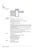
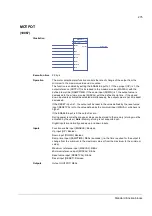
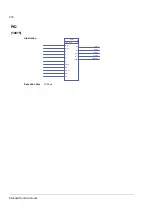
Illustration
Execution time
4.50 µs
Operation
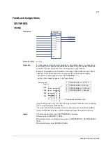
A critical speeds function block is available for applications where it is necessary to
avoid certain motor speeds or speed bands because of e.g. mechanical resonance
problems. The user can define three critical speeds or speed bands.
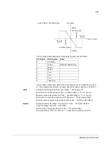
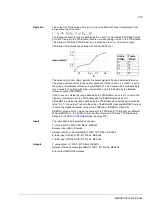
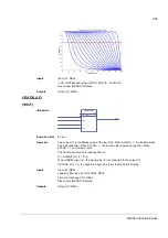
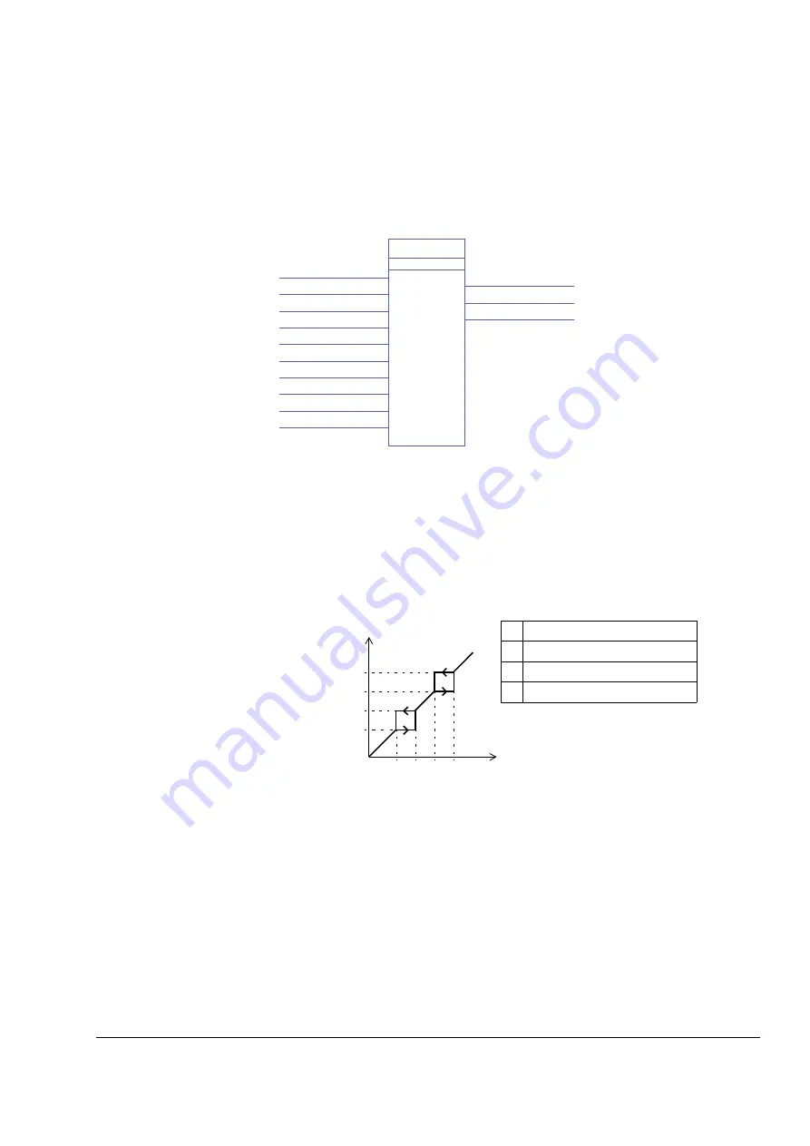
Example: An application has vibrations in the range of 540 to 690 rpm and 1380 to
1560 rpm. To make the drive made to jump over the vibration speed ranges:
- activate the critical speeds function (CRITSPEEDSEL = 1),
- set the critical speed ranges as in the figure below.
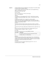
Output OUTACTIVE is set to 1 when the output reference (REFOUTPUT) is different
from the input reference (REFINPUT).
The output is limited by the defined minimum and maximum limits (MIN and MAX).
Output OUTSTATE indicates in which critical speed range the operation point is.
Inputs
Critical speed activation input (CRITSPEEDSEL): Boolean
Reference input (REFINPUT): REAL
Minimum/maximum critical speed range input (CRITSPEEDNLO / CRITSPEEDNHI):
REAL
Minimum/maximum input (MIN/MAX): REAL
CRITSPEED
57
TLA1 1 msec
(1)
CRITSPEEDSEL
CRITSPEED1LO
CRITSPEED1HI
CRITSPEED2LO
CRITSPEED2HI
CRITSPEED3LO
CRITSPEED3HI
MAX
MIN
REFINPUT
REFOUTPUT
REFOUTPUT (57)
OUTSTATE
OUTSTATE (57)
OUTACTIVE
OUTACTIVE(57)
Drive speed reference (rpm)
540
690
1380
1560
Motor speed
1
CRITSPEED1LO = 540 rpm
2
CRITSPEED1HI = 690 rpm
3
CRITSPEED2LO = 1380 rpm
4
CRITSPEED2HI = 1560 rpm
1 2 3 4
(rpm)
Summary of Contents for ACSM1 Series
Page 1: ...ACSM1 Firmware Manual ACSM1 Speed and Torque Control Program...
Page 2: ......
Page 4: ......
Page 12: ...Table of contents 12...
Page 49: ...Drive control and features 49...
Page 282: ...Standard function blocks 282...
Page 306: ...Application program template 306...
Page 312: ...Control chain block diagrams 312...
Page 331: ...331...
Page 332: ...332...
Page 333: ......

