Drive control and features
37
Motor control features
Scalar motor control
It is possible to select scalar control as the motor control method instead of Direct
Torque Control (DTC). In scalar control mode, the drive is controlled with a frequency
reference. However, the outstanding performance of DTC is not achieved in scalar
control.
It is recommended to activate the scalar motor control mode in the following
situations:
• In multimotor drives: 1) if the load is not equally shared between the motors, 2) if
the motors are of different sizes, or 3) if the motors are going to be changed after
motor identification (ID run)
• If the nominal current of the motor is less than 1/6 of the nominal output current of
the drive
• If the drive is used without a motor connected (for example, for test purposes)
• If the drive runs a medium-voltage motor through a step-up transformer.
In scalar control, some standard features are not available.
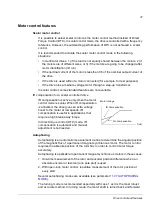
IR compensation for a scalar controlled drive
IR compensation is active only when the motor
control mode is scalar. When IR compensation
is activated, the drive gives an extra voltage
boost to the motor at low speeds. IR
compensation is useful in applications that
require a high break-away torque.
In direct torque control (DTC) mode, IR
compensation is automatic and manual
adjustment is not needed.
Autophasing
Autophasing is an automatic measurement routine to determine the angular position
of the magnetic flux of a permanent magnet synchronous motor. The motor control
requires the absolute position of the rotor flux in order to control motor torque
accurately.
Autophasing is applicable to permanent magnet synchronous motors in these cases:
1. One-time measurement of the rotor and encoder position difference when an
absolute encoder or resolver (one pole pair) is used
2. With open-loop motor control, repetitive measurement of the rotor position at
every start.
Several autophasing modes are available (see parameter
The turning mode is recommended especially with case 1 as it is the most robust
and accurate method. In turning mode, the motor shaft is turned back and forward
f
(Hz)
Motor voltage
No compensation
IR Compensation
Summary of Contents for ACSM1 Series
Page 1: ...ACSM1 Firmware Manual ACSM1 Speed and Torque Control Program...
Page 2: ......
Page 4: ......
Page 12: ...Table of contents 12...
Page 49: ...Drive control and features 49...
Page 282: ...Standard function blocks 282...
Page 306: ...Application program template 306...
Page 312: ...Control chain block diagrams 312...
Page 331: ...331...
Page 332: ...332...
Page 333: ......

