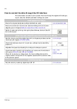
Drive control and features
42
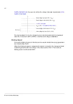
; the user can define the voltage manually at parameter
.
The intermediate DC circuit is charged over an internal resistor which is bypassed
when the correct level (80% of UDC) is reached and voltage is stabilised.
Braking chopper
The built-in braking chopper of the drive can be used to handle the energy generated
by a decelerating motor.
When the braking chopper is enabled and a resistor connected, the chopper will start
conducting when the DC link voltage of the drive reaches 780 V. The maximum
braking power is achieved at 840 V.
Undervoltage control level (0.74 ×
U
DC
)
Undervoltage trip level (0.65 ×
U
DC
)
Overvoltage control level (1.50 ×
U
DC
)
Overvoltage trip level (1.63 ×
U
DC
)
50 V min
U
DC
(1.35 ×
)
Summary of Contents for ACSM1 Series
Page 1: ...ACSM1 Firmware Manual ACSM1 Speed and Torque Control Program...
Page 2: ......
Page 4: ......
Page 12: ...Table of contents 12...
Page 49: ...Drive control and features 49...
Page 282: ...Standard function blocks 282...
Page 306: ...Application program template 306...
Page 312: ...Control chain block diagrams 312...
Page 331: ...331...
Page 332: ...332...
Page 333: ......

