Drive control and features
46
Mechanical brake
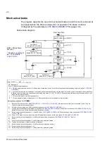
The program supports the use of a mechanical brake to hold the motor and load at
zero speed when the drive is stopped or not powered. The brake control is
configured by the parameters in
(page
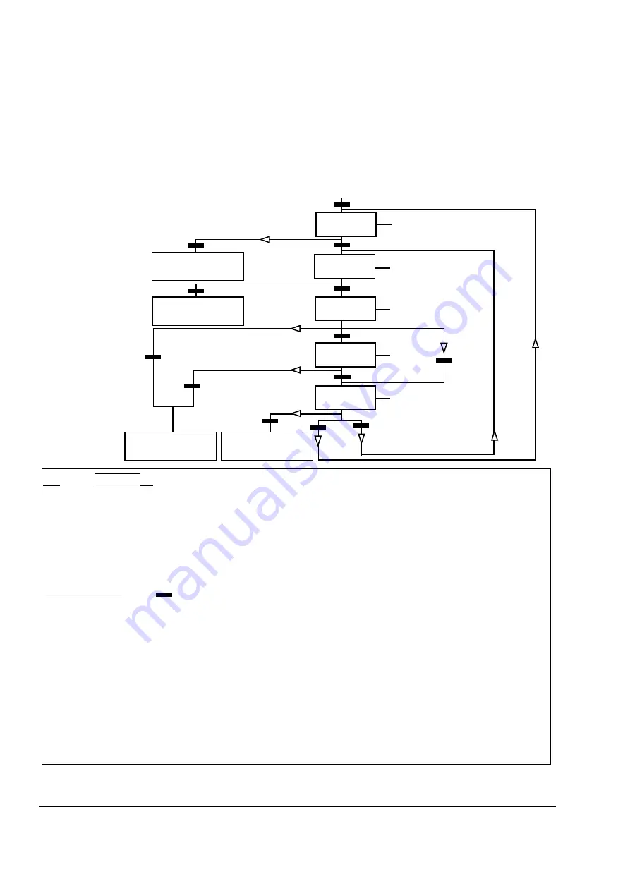
Brake state diagram
CLOSE
BRAKE
From any state
0/1/1/0
1/1/1/1
1)
2)
3)
6)
7)
11)
12)
13)
5)
0/0/1/1
8)
State (Symbol
)
- NN: State name
- W/X/Y/Z: State outputs/operations
W: 1 = Brake open command is active. 0 = Brake close command is active. (Controlled through selected digital/relay output with signal
X: 1 = Forced start (inverter is modulating). The function keeps the internal Start on until the brake is closed in spite of the status of the external Stop.
Effective only when ramp stop has been selected as the stop mode (
). Run enable and faults override the forced start. 0 = No
forced start (normal operation).
Y:
1 = Drive control mode is forced to speed/scalar.
Z:
1 = Ramp generator output is forced to zero. 0 = Ramp generator output is enabled (normal operation).
NN
W/X/Y/Z
State change conditions (Symbol
)
1)
Brake control is active (
) OR modulation of the drive is requested to stop. The drive
control mode is forced to speed/scalar.
2)
External start command is on AND brake open request is on (
= 0).
3)
Starting torque required at brake release is reached (
) AND brake hold is not active (
Note:
With scalar control, the defined starting torque has no effect.
4)
Brake is open (acknowledgement = 1, selected by par.
) AND the brake open delay has passed (
). Start = 1.
5) 6) Start = 0 OR brake close command is active AND actual motor speed < brake close speed (
).
7)
Brake is closed (acknowledgement = 0) AND brake close delay has passed (
). Start = 0.
8)
Start = 1.
9)
Brake is open (acknowledgement = 1) AND brake close delay has passed.
10)
Defined starting torque at brake release is not reached.
11)
Brake is closed (acknowledgement = 0) AND brake open delay has passed.
12)
Brake is closed (acknowledgement = 0).
13)
Brake is open (acknowledgement = 1) AND brake close delay has passed.
0/1/1/1
Fault/Alarm*
BRAKE NOT CLOSED
9)
Fault/Alarm*
BRAKE START TORQUE
10)
4)
BSM = Brake State
Machine
* Depends on setting of
par.
BSM STOPPED
BSM
START
1/1/0/0
RELEASE
RAMP
OPEN
BRAKE
Fault/Alarm*
BRAKE NOT CLOSED
Fault/Alarm*
BRAKE NOT OPEN
Summary of Contents for ACSM1 Series
Page 1: ...ACSM1 Firmware Manual ACSM1 Speed and Torque Control Program...
Page 2: ......
Page 4: ......
Page 12: ...Table of contents 12...
Page 49: ...Drive control and features 49...
Page 282: ...Standard function blocks 282...
Page 306: ...Application program template 306...
Page 312: ...Control chain block diagrams 312...
Page 331: ...331...
Page 332: ...332...
Page 333: ......

