background image

10

A DS 4 20

  |  D I SS O LV ED OX YG EN SEN S O R  |  O I/A DS 4 2 0 - EN R E V. B

…4  Calibration

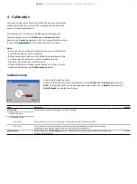
2-Point calibration (100 % and 0 % saturation)

Note . 

This calibration procedure requires 60 mL (2.0 US fl oz) 

of fresh sodium sulfite solution.

Using a customer-supplied calibration pot, place a wetted 
sponge at the bottom of the container.

Ensure the probe and sensing element are completely dry. If 
necessary use a paper towel to remove any water or debris 
from the probe or sensing element.

Slide probe into calibration chamber until the sensing 
element is approximately 25 mm (1 in) above water-saturated 
sponge.

Allow 5 to 10 minutes for temperature stabilization prior to 
continuing the calibration procedure.  

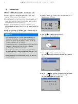
NOTICE

•  Do not leave the probe in the calibration chamber for 

more than 30 minutes – this can allow condensation to 

form on the surface of the sensing element, producing 
false low readings after calibration. 

•  If condensation occurs, remove the probe, thoroughly dry 

the sensing element, probe and thermistor before 
performing the calibration procedure. 

•  Ensure the calibrations are performed in a vented but 

enclosed chamber, to prevent pressure building up in the 
container. 

•  Minimize ambient airflow across the sensor head during 

the calibration.

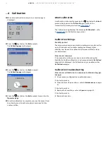
At the transmitter perform a 2-point calibration from an 
Operator page as follows:

CAL

2014–08–20

10:34:52

7.62

25

°C

ppm 

Dissolved Oxygen

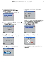
Press the 

 key (below the 

Cal

 prompt).  

The Calibrate page is displayed:

Calibrate

Menu

Exit

Select

Press the 

 key (below the 

Select

 prompt).  

The 

Calibrate

 page is displayed with all available sensors 

shown:

Calibrate

S1: DO

Back

Select

Use the 

/

 keys to select the probe to be calibrated and 

press the 

 key (below the 

Select

 prompt).  

The 

Calibration Type

 page is displayed:

S1: DO

Next

Edit

Calibration Type

2-Point Cal

Summary of Contents for ADS420

Page 1: ...ional EZClean compressed air supply unit connected to an ABB adapter nozzle or T piece a schedule can be configured to provide automatic in situ cleaning of the sensor For more information Further publications and publications for the associated AWT420 and AWT440 transmitters are available for free download from www abb com measurement or by scanning this code Search for or click on Data Sheet ADS...

Page 2: ...libration 100 and 0 saturation 10 Abort calibration 12 Calibration timings 12 Stability period 12 Slow sensor response 12 Calibration troubleshooting 12 Slow sensor calibration or no response to dissolved oxygen changes 12 5 Maintenance 13 Cleaning the SmartCap 13 Cleaning the lens 13 Cleaning the sensor body 14 6 Diagnostics 15 S n PT failure 15 S n D O Conc Meas Error 15 S n Sat Meas Error 15 S ...

Page 3: ... below Direct current supply only This symbol identifies a risk of chemical harm and indicates that only individuals qualified and trained to work with chemicals should handle chemicals or perform maintenance on chemical delivery systems associated with the equipment This symbol indicates the need for protective eye wear This symbol indicates the need for protective hand wear Recycle separately fr...

Page 4: ...tablish and maintain any appropriate measures such as but not limited to the installation of firewalls application of authentication measures encryption of data installation of anti virus programs etc to protect the product the network its system and the interface against any kind of security breaches unauthorized access interference intrusion leakage and or theft of data or information ABB and it...

Page 5: ...ner Note The SmartCap serial number is programmed on the memory chip inside the SmartCap D Sensor body including temperature sensor E 10 m 39 3 ft fixed cable ADS420 cable detached ADS420 sensor components cable detached are shown in Figure 2 Figure 2 ADS420 sensor components cable detached Table 2 Sensor components cable detached Part Description A EZLink digital sensor connector B Shroud C Smart...

Page 6: ...type None Low Medium High None Salinity Unit Select the required salinity units PSU Practical Salinity Units or ppt parts per thousand PSU Salinity Correction Required when monitoring water containing high quantities of dissolved salts enter the required value between 0 and 42 Practical Salinity Units PSU leave at the default value of 0 PSU if salinity correction is not required 0 PSU Pressure Uni...

Page 7: ...n After calibration and sensor replacement reset the currents outputs and alarms see Calibrate menu below Calibrate menu Calibrate Menu Exit Select Used to calibrate the sensor Access to the Calibrate menu is permitted via the Calibrate and Advanced levels only Note During calibration current outputs and alarms are set to Hold automatically if Hold Outputs is enabled see below Menu Comment Default...

Page 8: ...ement producing false low readings after calibration If condensation occurs remove the sensor thoroughly dry the sensing element probe and thermistor before performing the calibration procedure Ensure the calibrations are performed in a vented but enclosed chamber to prevent pressure building up in the container Minimize ambient airflow across the sensor head during the calibration 5 At the transm...

Page 9: ...t Span Cal Place in 100 Sat Abort Continue 12 Press the key below the Continue prompt The Calibrate page is displayed Calibrate PV 98 26 Tmp 25 22 C Setting Please Wait Abort 13 When span calibration is complete a results page is displayed Calibrate PV 98 98 Tmp 24 90 C Offset 0 045 Slope 1 054 Exit In the event of a calibration failure the message Calibration Failed is displayed with an indicatio...

Page 10: ...nsation to form on the surface of the sensing element producing false low readings after calibration If condensation occurs remove the probe thoroughly dry the sensing element probe and thermistor before performing the calibration procedure Ensure the calibrations are performed in a vented but enclosed chamber to prevent pressure building up in the container Minimize ambient airflow across the sen...

Page 11: ...n 100 Sat Abort Continue 12 Press the key below the Continue prompt The Calibrate page is displayed Calibrate PV 98 26 Tmp 25 22 C Setting Please Wait Abort 13 When span calibration is complete the Calibrate Start Zero Cal page is displayed Calibrate Start Zero Cal Place in 0 Sat Abort Continue 14 Remove the sponge wafer from the calibration pot 15 Fill calibration chamber with fresh sodium sulfit...

Page 12: ...perating Instructions OI AWT420 The Calibration Log displays the message Cal Aborted refer to OI AWT420 for Calibration Log entries Calibration timings Stability period The temperature and concentration readings are monitored for up to 10 minutes until a stable reading is achieved When stability is achieved the calibration slope and offset values are determined Slow sensor response If the output f...

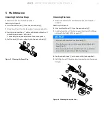
Page 13: ... Figure 3 Cleaning the SmartCap Cleaning the lens 1 Isolate the transmitter and remove the sensor from the process Referring to Figure 4 2 Unscrew the shroud A from the sensor body B 3 Grip the SmartCap C between your thumb and forefinger and carefully slide it off the sensor D NOTICE Do not touch the end of the SmartCap C Do not allow moisture or atmospheric humidity inside SmartCap C Do not wet ...

Page 14: ...ate the transmitter and remove the sensor from the process Referring to Figure 5 2 Gently scrub the shroud A and the sensor body B with a soft bristled brush or a nylon dish scrubber If it is necessary use a grease remover to remove grease or other matter from the sensor body or soak in vinegar and deionized water to remove mineral deposits or extensive fouling Figure 5 Cleaning the sensor body ...

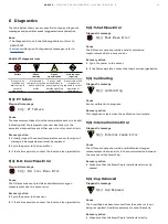
Page 15: ... 3 If the failure persists contact the local service organization S n D O Conc Meas Error Diagnostic message S n D O Conc Meas Error Cause The DO sensor cannot provide a valid dissolved oxygen measurement due to a sensor error Recovery action 1 Cycle the power to the sensor 2 If the failure persists contact the local service organization S n Sat Meas Error Diagnostic message S n Sat Meas Error Cau...

Page 16: ...sor Warm up Diagnostic message S n Sensor Warm up Cause The DO sensor is warming up and cannot provide a valid DO measurement until the internal electronics have stabilized Recovery action This diagnostic clears when the internal electronics have stablized If the diagnostic persists contact the local service organization S n Sensor Warning Diagnostic message S n Sensor Warning Cause PV measured fr...

Page 17: ...nostic message S n Replace Cap Cause The SmartCap in the DO sensor reaches its expiry date within 4 weeks After its expiry date the SmartCap may continue to operate but its accuracy degrades and cannot be guaranteed to meet specification Recovery action 1 Replace the SmartCap ...

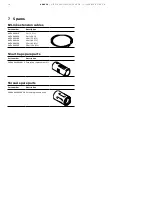
Page 18: ...n AWT4009010 AWT4009050 AWT4009100 AWT4009150 AWT4009250 AWT4009500 1 m 3 3 ft 5 m 16 4 ft 10 m 32 8 ft 15 m 49 2 ft 25 m 82 0 ft 50 m 164 0 ft SmartCap spare parts Part number Description 3KXA494400L0019 SmartCap replacement kit Shroud spare parts Part number Description 3KXA494400L0020 Shroud replacement kit ...

Page 19: ...ADS420 DISSOLVED OX YGEN SENSOR OI ADS420 EN REV B 19 Acknowledgements EZLink is a trademark of ABB Limited ...

Page 20: ...h regard to purchase orders the agreed particulars shall prevail ABB does not accept any responsibility whatsoever for potential errors or possible lack of information in this document We reserve all rights in this document and in the subject matter and illustrations contained therein Any reproduction disclosure to third parties or utilization of its contents in whole or in parts is forbidden with...

Reviews: