8
Adjustable flanges to various standard drilling configurations are
also available to mount dip models close to a closed tank wall.
Note.
Flanges available are very diverse. Please
consult the sales office for details.
…3
MECHANICAL INSTALLATION
1000
mm (39
3
/
8
in) or 2000
mm (79
3
/
4
in)
11
7
mm (4
5
/
8
in)
75 mm (3 in)
71.5 mm
Dia
(2
13
/
16
in)
35 mm
(1
3
/
8
in)
50.8 mm
(2 in)
25 mm
(1in)
44
mm
(1
3
/
4
in)
64
mm
(2
1
/
2
in)
79
mm
(3
1
/
8
in)
102 mm
(4 in)
4 Holes 8.0mm Dia (
5
/
16
in)
WALL MOUNTING CLAMP
pt. no. 7604 440
One clamp for 1 metre models,
two clamps for 2 and 3 metre
models.
Maximum immersion depth
203 mm (8 in)
93 mm (3
11
/
16
in)
52
mm (2
3
/
64
in)
George Fischer
Flange Adaptor
Pt No.735-810-108
Two Fixing Holes
M10 x 1.5 on
44 mm (1
3
/
4
in)
Centres
70 mm (2
3
/
4
in)
222
mm (8
3
/
4
in)
Allow about 150 mm (6 in)
free space above the top
cover for access and
removal of the cover.
2 in Flange BS 10 Table E
152
mm (6
in)
198.5 mm (7
13
/
16
in)
222
mm (8
3
/
4
in)
Allow about 150 mm (6 in)
free space above the top
cover for access and
removal of the cover.
3.2.2
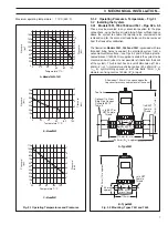
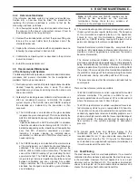
Model 7652 – Fig. 3.3
This is installed and held in position by the 2 in BS10 Table E fixing
flange only.
3.2.3
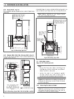
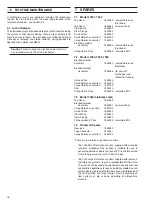
Models 7654, 7655, 7656, 7664 and 7665 – Fig. 3.4
These are dip systems installed in any convenient position over
the open tank or channel.
3.3
Fitting Electrodes –
Figs. 3.6, 3.7, 3.8, 3.9 and 3.10
Note
.
• Ensure that the system cable is fed through the
electrode system cover or dip tube, as applicable,
before the cable is connected.
• Secure the cable in its permanent position,
ensuring sufficient free cable at both ends for
connection to the electrodes and to the meter.
Caution.
To avoid the risk of damp or corrosive air
damaging the cable plugs, connect to the electrodes
as soon as possible.
3.3.1
Removing the Sensor Holder
Note.
Reservoir-fed systems: only follow instructions
with respect to Flow/In-Line systems, then refer to
Section 3.4 to fit the reservoir assembly.
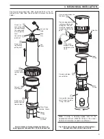
Fig. 3.3 Mounting, Type 7652
Fig. 3.4 Mounting, Types 7654, 7655, 7656,7664 and 7665
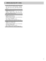
Fig. 3.5 Mounting, Type 7661


