Single and Dual Input Analyzers for pH/Redox (ORP)
AX416, AX436, AX460, AX466 & AX468
7 CALIBRATION
58
IM/AX4PH
Issue 9
7.3 Factory Settings
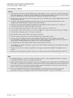
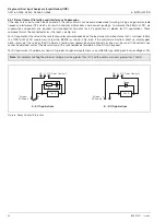
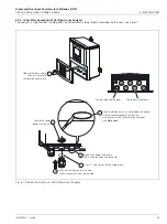
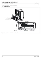
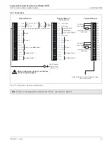
Fig. 7.1 Analyzer Terminal Links and Decade Resistance Box Connections
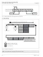
Fig. 7.2 Overall Factory Settings Chart
Note.
The Option Board page is displayed only if the option board is fitted.
Terminal link
pH/Redox
Input Simulator
Temperature
Simulator
B10
B11
B12
B13
B14
B9
Sensor A Terminal Numbers
Sensor B Terminal Numbers
B2
B3
B4
B5
B6
B1
B15
B16
B7
B8
–ve
+ve
FACTORY SETTINGS
Factory Set Code
Cal. Sensor A
A:mV Zero (-1V)
A:mV Span (+1V)
A:T.Zero (100R)
A:T.Span (150R)
Cal. Sensor B
B:T.Zero (100R)
B:T.Span (150R)
Cal. Output 1
O1: Adjust 4mA
O1: Adjust 20mA
To
OPERATING PAGE
A:T.Zero (1K0)
B:T.Zero (1K0)
A:T.Span (1K5)
B:T.Span (1K5)
Available only if the Option Board is fitted
and
Analog features enabled – see page 61
Key
Cal. Output 3
Cal. Output 4
O3: Adjust 4mA
O4: Adjust 4mA
O3: Adjust 20mA
O4: Adjust 20mA
Cal. Output 2
O2: Adjust 4mA
O2: Adjust 20mA
Use the Sidescroll Key to scroll through the Pages within each Menu
Use the Menu
Key to scroll
through
the Menus
Use the Downscroll
Key to scroll through
the Frames
within each Page
Section 7.3, Page 58
A:T.Span (5K0)
A:T.Zero (2K0)
B:mV Span (+1V)
B:T.Zero (2K0)
B:T.Span (5K0)
B:mV Zero (-1V)
Dual input analyzer only
Alter Fact.Code
Option Board
Note.
The
Option Board
page is
displayed only if the Option Board is fitted.


