AquaMaster 3 FET200
Electromagnetic flowmeter Transmitter
3 Electrical Installation
14
OI/FET200–EN Rev. I
3 Electrical Installation
3.1 Grounding
Note.
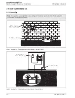
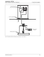
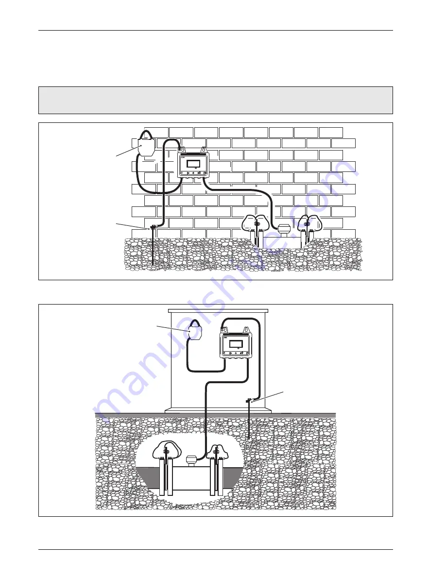
The grounding arrangements shown in Figs 3.1 to 3.3 are applicable to both cathodic and
non-cathodic protected installations.
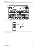
Fig. 3.1 AquaMaster3 Transmitter Mounted in a Chamber – Flanged Sensor
Fig. 3.2 AquaMaster3 Transmitter Mounted in a Cabinet – Flanged Sensor
A
quaMa
s
ter
3
Battery (Shown) or
Mains Power Supply
Earth (Ground) Rod
A
quaMa
s
ter
3
Battery (Shown) or
Mains Power Supply
Earth (Ground) Rod

