AquaMaster 3 FET200
Electromagnetic flowmeter Transmitter
3 Electrical Installation
24
OI/FET200–EN Rev. I
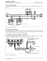
3.4.4 Termination Resistor
To minimize transmission line travelling wave reflections caused by impedance discontinuities at the end of
the described RS485-cable a Line Termination is required near each of the 2 ends of the 'Bus' as described
in the MODBUS over Serial Line – Specification and Implementation Guide V1.02 – see page 22.
3.4.5 Cable Properties
An RS485-MODBUS configuration without repeater has one trunk cable or 'Bus', along which devices are
connected directly (daisy chaining) or by short 'tap' cables. The use of repeaters between several
RS485-MODBUS is also possible.
The end-to-end length of the trunk cable must be limited. The maximum length depends on the Baud rate,
the cable (gauge, capacitance or characteristic impedance), the number of loads on the daisy chain and
the network configuration (2-wire or 4-wire).
For 9600 Baud rate and AWG26 (or wider) gauge, the maximum length is 1000 m (3280 ft.). Where 4-wire
cabling is used as a 2-wire cabling system the maximum length must be divided by 2.
The 'tap' cables must be short and never more than 20 m (65.6 ft.). If a multi-port tap is used with n
derivations, each one must have a maximum length of 40 m (131 ft.) divided by n.
The maximum serial data transmission line length for RS485 systems is 1200 m (3937 ft.). The lengths of
cable that can be used are determined by the cable type, typically:
Up to 6 m (19.7 ft.) – standard screened or twisted pair cable.
Up to 300 m (984 ft.) – twin twisted pair with overall foil screen and an integral drain wire – for
example, Belden 9502 or equivalent.
Up to 1200 m (3937 ft.) – twin twisted pair with separate foil screens and integral drain wires – for
example, Belden 9729 or equivalent.
Category 5 cables may be used for RS485-MODBUS to a maximum length of 600 m (1968 ft.).
For the balanced pairs used in an RS485-system, a characteristic impedance with value higher than 100
is preferred, especially for 19200 and higher Baud rates.
Fig. 3.16 Termination Resistor Location
150
Terminating
Resistor
Last
Last
Slave
Master
Host Computer
A
B
C
150
Terminating
Resistor


