background image

AquaMaster 3 FET200

Electromagnetic flowmeter Transmitter

3 Electrical Installation

26

OI/FET200–EN Rev. I

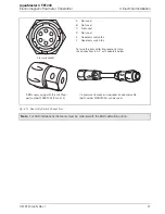
Fig. 3.17 Internal Battery Pack (Integral Transmitters Only)

B

C

A

D

E

+

+

Summary of Contents for AquaMaster 3 FET200

Page 1: ...his User Guide provides end user details for AquaMaster 3 close coupled and remote transmitters When the meter is taken out of storage and installed for first use remove the protective label if fitted from the front to enable light to activate the unit If the meter is not powered connect any batteries or external supply as detailed in this manual For a comprehensive overview of publications availa...

Page 2: ...ompany s products result from over 100 years experience combined with a continuous program of innovative design and development to incorporate the latest technology Quality Control The UKAS Calibration Laboratory No 0255 is just one of the ten flow calibration plants operated by the Company and is indicative of our dedication to quality and accuracy UKAS Calibration Laboratory No 0255 For more inf...

Page 3: ... 3 1 Grounding 14 3 2 Connections 16 3 2 1 AquaMaster3 Sensor Connections Remote or Close Coupled only 16 3 2 2 Using Tamper Detection Seals 16 3 3 Input Output Connections 17 3 3 1 Frequency Outputs 17 3 3 2 Alarm Interface 17 3 3 3 Input Output Connections 18 3 3 4 ScanReader Interface Option 19 3 3 5 RS232 Local Computer Connection 19 3 3 6 Pressure Transducer Optional 20 3 3 7 Anti tamper Prot...

Page 4: ...Sockets 30 4 4 1 Service Intervals 30 4 4 2 Equipment Required 31 4 4 3 Preparation 31 4 4 4 Disconnection 31 4 4 5 Order of Treatment 32 4 4 6 Stage 1 Oxide Removal and Cleaning 32 4 4 7 Stage 2 Oxide Prevention 33 4 4 8 Completion tasks 33 5 Specification 34 Appendix A GSM Equipped Units Safety Precautions 39 Appendix B Accessories Spares Kits 40 B 1 Common accessories 40 B 2 Adapter Cable Upgra...

Page 5: ...IEC 61010 1 2010 Safety Requirements for Electrical Equipment for Measurement Control and Laboratory Use and complies with US NEC 500 and Occupational Safety Health Administration If the equipment is used in a manner NOT specified by the Company the protection provided by the equipment may be impaired 1 2 Symbols One or more of the following symbols may appear on the equipment labelling Warning Re...

Page 6: ... Normal safe handling procedures must be used When disposing of chemicals ensure that no two chemicals are mixed Safety advice concerning the use of the equipment described in this manual or any relevant hazard data sheets where applicable may be obtained from the Company contact details on the back cover together with servicing and spares information Warning Installation and maintenance must be c...

Page 7: ...T200 EN Rev I 5 2 Mechanical Installation 2 1 Installation Conditions Fig 2 1 Siting Fig 2 2 Within Temperature Limits Fig 2 3 Shade Fig 2 4 Vibration Fig 2 5 Spillage Close coupled version allow room to read data plate AquaMaster3 60 C 140 F Maximum 20 C 4 F Minimum AquaMaster3 AquaMaster3 ...

Page 8: ...to Transmitter Fig 2 8 Pressure Transducer Protect from Frost AquaMaster3 2 m 78 in Submerged 9 Months Accrued Time IP68 NEMA 6P ENCLOSURE 6P Not applicable to GSM Integral Aerial Installations see Section 2 4 1 page 10 AquaMaster3 AquaMaster3 For access to display and communication connector AquaMaster3 AquaMaster3 Pressure Transducer Pressure Transducer ...

Page 9: ...tallation OI FET200 EN Rev I 7 2 2 Fitting the Vandal Resistant Housing Integral Transmitters Only Referring to Fig 2 9 1 Slide cover A over transmitter 2 Insert bottom plate B ensuring clips C enter lugs D 3 Secure with lock E Fig 2 9 Fitting Anti Vandal Housing AquaMaster 3 ...

Page 10: ...00 EN Rev I 2 3 Dimensions 2 3 1 Remote and Close Coupled Transmitter Dimensions in mm in Fig 2 10 AquaMaster3 Dimensions AquaMaster3 Ø 6 5 0 25 Ø13 0 50 115 4 50 177 7 0 50 2 0 185 7 3 28 1 1 136 5 4 Remote mounted Transmitter Close coupled Transmitter 105 4 1 280 11 0 with Connectors 125 5 0 ...

Page 11: ...External Battery Pack Dimensions in mm in Fig 2 11 Integral Transmitter Dimensions Dimensions in mm in Fig 2 12 Vandal resistant housing dimensions Dimensions in mm in Fig 2 13 AquaMaster3 Battery Pack Dimensions AquaMaster3 175 6 9 160 6 3 135 5 3 225 8 9 244 9 6 220 8 7 175 3 9 214 8 4 191 7 5 184 7 2 182 7 2 225 8 9 260 10 2 178 7 0 150 5 90 76 3 0 148 5 83 9 0 35 ...

Page 12: ...um of 2 visible signal strength indicator bars are recommended For SMS text a minimum of 1 visible signal strength indicator bar is recommended The following must also be observed when deciding on the antenna mounting location For best results mount the antenna as high above local ground level as possible If the antenna must be mounted below ground achieve optimum results by ensuring there is a st...

Page 13: ...ic flowmeter Transmitter 2 Mechanical Installation OI FET200 EN Rev I 11 Fig 2 14 GSM Antenna Installation Fig 2 15 GSM Antenna Installation AquaMaster3 AquaMaster3 Remote Antenna Integral Antenna 50 mm 2 0 in 50 mm 2 0 in 50 mm 2 0 in ...

Page 14: ...x 4 mm Hex fixing screws A and remove the transmitter 3 Use water to wash off any loose dirt from the case and dry the area around the SIM card cover 4 On the back of the transmitter unscrew and remove cover B protecting SIM card holder C 5 If the SIM card is being changed ensure the GSM Engine is off before removing the card by reading 368 see COI FET2XX EN and ensuring the status reported is Off...

Page 15: ...ntil it clicks into place and refit cover B 9 Screw cover B firmly in place 10 Refit the transmitter to its mounting point 11 Position the transmitter on the integral mount and secure with 4 x 4 mm Hex fixing screws A Tighten the screws to 4Nm Note Step 10 is applicable only to remote and close coupled transmitters Note Step 11 is applicable only to integral transmitters Fig 2 17 Installing a SIM ...

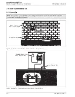
Page 16: ...gements shown in Figs 3 1 to 3 3 are applicable to both cathodic and non cathodic protected installations Fig 3 1 AquaMaster3 Transmitter Mounted in a Chamber Flanged Sensor Fig 3 2 AquaMaster3 Transmitter Mounted in a Cabinet Flanged Sensor AquaMaster3 Battery Shown or Mains Power Supply Earth Ground Rod AquaMaster3 Battery Shown or Mains Power Supply Earth Ground Rod ...

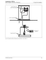
Page 17: ...lowmeter Transmitter 3 Electrical Installation OI FET200 EN Rev I 15 Fig 3 3 AquaMaster3 Transmitter Mounted in a Cabinet Probe Sensor AquaMaster3 Probe Sensor Ground Battery Shown or Mains Power Supply Earth Ground Rod Bond Probe to Pipe ...

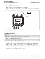
Page 18: ... it engages then tighten the locking ring 3 2 2 Using Tamper Detection Seals Referring to Fig 3 5 1 Pass the wire of the seal through both the hole in the locking ring and the matching hole in the front of the transmitter 2 Close the seal Note Refer to Section Fig 3 4 page 22 for MODBUS connection Note If the sensor cable is terminated with fly leads connection is via a sensor cable adapter box pa...

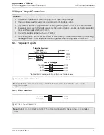
Page 19: ...loads must be inrush current limited Fully floating pulse outputs may be subject to static damage for example connecting to a floating datalogger unless COM is operated within its galvanic isolation range 35 V from earth Fig 3 6 Frequency Output Connections Note Outputs 1 and 2 are not polarity sensitive The common connection for these outputs is designated COM Fig 3 7 Alarm Output Connections Not...

Page 20: ...n Signal Function Color Output Cable A Not used Not used Violet B DATA ScanReader Data Blue C O P COM Output Common Yellow D O P2 Reverse Pulses or Direction Indicator Red E O P3 Alarm Output Brown F O P1 Forward Pulses or Forward Reverse Pulses Orange G 0V Scanreader 0V Screen Table 3 1 Connector Input Output Connections WABC 2010 A B C D E F G Pin View I O Socket only ...

Page 21: ...n or wired with voltages applied unnecessarily Such voltages result in far higher power consumption from the battery or backup source limiting battery backup life The serial port connection shares the same physical port as the MODBUS connection so depending on cable design it may be necessary to disconnect the MODBUS connection temporarily to enable configuration of AquaMaster3 Reading Pad 3 Wire ...

Page 22: ...nstruments Directive MID 2004 22 EEC or OIML R49 the flowmeter can be sealed to prevent unauthorized changes to the meter settings and configuration A read only switch link is used see Fig 3 12 to prevent login through any communication means and modification of any parameters on the AquaMaster3 Fig 3 11 Optional Pressure Transducer Connector Caution Use only the pressure transducer supplied with ...

Page 23: ...with the MID calibration option A Not used B Not used C Not used D Not used E Read only switch link F Read only switch link To force the transmitter into read only state link connections E F or fit adapters below ABB supply a plug with this link fitted part number WEBC2054 Pack of 5 If a pressure transducer is required an adapter cable part number WEBC2025 can be used D A B F E C Pressure socket ...

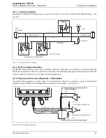
Page 24: ...tained in the following external publications MODBUS over Serial Line Specification and Implementation Guide V1 02 Dec 20 2006 http www modbus org Refer to this guide for hardware cabling grounding and shielding on MODBUS MODBUS Application Protocol Specification V1 1b Dec 28 2006 http www modbus org Fig 3 13 MODBUS Connection Note A USB Comms lead driver is required when using WEBC2100 download f...

Page 25: ...e signal immunity to noise pick up if the data is to be taken over long distances 3 4 3 Pull up and Pull down Resistors Polarization To prevent false triggering of slaves when the master host computer is inactive pull up and pull down resistors must be fitted to the RS485 interface at the host computer see Fig 3 15 Fig 3 14 General 2 Wire Topology Fig 3 15 Host Computer Interface Master 5 V Slave ...

Page 26: ...auge the maximum length is 1000 m 3280 ft Where 4 wire cabling is used as a 2 wire cabling system the maximum length must be divided by 2 The tap cables must be short and never more than 20 m 65 6 ft If a multi port tap is used with n derivations each one must have a maximum length of 40 m 131 ft divided by n The maximum serial data transmission line length for RS485 systems is 1200 m 3937 ft The ...

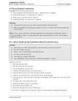
Page 27: ...arity as shown in Fig 3 17 page 26 8 Fit 3 new cells to the top level of the pack 9 Carefully refit battery pack C to enclosure 10 Reconnect battery connector B 11 Place new silica gel bag on top of battery pack 12 Ensuring O ring seal and O ring groove is clean refit enclosure lid A and tighten finger tight Warning Disconnect the supply from any cables being terminated on the transmitter Electric...

Page 28: ...AquaMaster 3 FET200 Electromagnetic flowmeter Transmitter 3 Electrical Installation 26 OI FET200 EN Rev I Fig 3 17 Internal Battery Pack Integral Transmitters Only B C A D E ...

Page 29: ... connections as shown in Fig 3 19 Note Before making connections check the Data label to confirm power supply requirements AquaMaster3 can be powered from Explorer style battery packs fitted with the MIL plastic style plug The Explorer battery capacity is 6 7 of published life Fig 3 18 Connecting a Battery Supply Note Before making connections check the Data label to confirm power supply requireme...

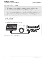
Page 30: ...tput regulator can be omitted if the off load voltage is below V in max Renewable energy generators do not operate at maximum capacity for example low wind speeds coating of the solar panel with dust and wildlife droppings and short daylight periods in winter For these reasons in some installations generators with a capacity greater then the specified 5 W minimum should be used Contact ABB for a t...

Page 31: ...ck used by AquaMaster3 may present a risk of fire or chemical burns if mistreated Do not recharge disassemble heat above 100 C 212 F or incinerate Replace battery pack with an ABB supplied part only Use of another battery may present a risk of fire or explosion Dispose of all battery packs promptly Keep away from children Dispose of battery packs in accordance with local regulations Where possible...

Page 32: ...r treatment of the gold connector pins 4 4 1 Service Intervals Treat all connectors at 3 year intervals when the battery pack is changed when the installation is visited for other reasons such as CalMaster 2 Verification Note To use local or remote serial communications for instructions on how to alter the displayed set of measurements and for meter setup refer to COI FET2XX EN Fig 4 1 AquaMaster3...

Page 33: ...d Uncap unused connectors Description Part No DeoxIT Contact Cleaner Rejuvenator DeoxIT Mini spray 5 solution flushing action 14 g Applications 150 approx D5MS 15 DeoxIT GOLD Contact Enhancer conditioner Protector DeoxIT GOLD G5 Mini Spray 5 solution 14 g flushing action and safe on plastics Applications 150 approx G5MS S Item Precaution Real time Clock This procedure may result in the loss of the...

Page 34: ...nections and cables 4 4 6 Stage 1 Oxide Removal and Cleaning To remove existing oxide and clean the pins 1 Apply a short burst around 0 5 second duration of DeoxIT DN5 spray to the metal surfaces of the connectors and to the gold connector pins 2 Connect a corresponding male female connector to the connector under test 5 times 3 Wait 10 seconds 4 Reapply one short burst around 0 5 s duration of De...

Page 35: ...pray to the metal surfaces 4 Allow any residue to run out of connector 5 Wait 30 seconds for the application to dry 4 4 8 Completion tasks To complete servicing of the plugs and sockets 1 Reconnect peripheral devices in this order a Sensor b Pressure transducer if fitted c Outputs d Communications e Battery pack power 2 Refit protective caps on unused connection sockets 3 For transmitters with bui...

Page 36: ...ble via adaptor box on application Mains supply 85 to 265 V AC 3 VA Connection cable approx 3 m 10 ft Mains power failure backup time Standard approx 5 days from internal super capacitor Optional up to 5 years with power cable option AS and external battery option AD Renewable power Solar or wind Input voltage 6 to 22 V DC 5 W Note Renewable energy generators do not operate at maximum capacity for...

Page 37: ...ches with common isolation 35 V DC 50mA Output 1 forward only or forward plus reverse pulses Output 2 reverse pulses or direction indicator Output 3 alarm indicates any problem with measurement or with power Pulse output 50 Hz maximum 50 nominal duty cycle Communications options Serial data communications Local Port RS232 Note On battery and renewable energy versions frequent use of the RS232 or R...

Page 38: ...y bands Quad band 850 900 1800 1900 MHz Functions SMS auto report of flow and optionally pressure logger data typically 1 s or 1 min average SMS report frequency typically daily SMS alarm reporting at time of event for example power loss limited to 1 per day SMS flowmeter configuration SMS flowmeter diagnosis SMS total tariff auto report GSM antenna option Quad band operation 850 900 1800 1900 MHz...

Page 39: ...ered 15 s battery powered external renewable energy Device languages English French German Spanish Italian Dutch Pressure system external transducer option Pressure range 16 bar Abs Connection Standard quick fit male probe connector via an adapter cable Operating temperature range 20 ambient to 70 C 4 to 158 F Protect the sample and transducer from freezing Accuracy typical 0 4 of range Thermal er...

Page 40: ...ssure Forward Reverse Tariffs Net Flow Totals No of Records 8831 11361 732 Logging Interval 15 to 65500 s adjustable 24 hr fixed Typical Capacity 3 months 15 minutes 7 days approx 1 minutes 2 years Software Direct RS232 SMS Text ABB AC800M ABB Generic for example LogMaster Areal Topkapi MasterVue I P AutoChart EcoTech HydroComp Mobile phone text OSI PI Database or Capula QTech Zeepaard Agua Ambien...

Page 41: ...arding an aircraft Remove the SIM card before shipping Make sure it cannot be switched on inadvertently The operation of wireless appliances in an aircraft is forbidden to prevent interference with communications systems Failure to observe these instructions may lead to the suspension or denial of cellular services to the offender legal action or both 3 Do not operate the cellular terminal or mobi...

Page 42: ...e WABC2010 10 10 m 32 8 ft for remote WABC2010 20 20 m 65 6 ft for remote WABC2010 30 30 m 98 4 ft for remote WABC2010 40 40 m 131 2 ft for remote WABC2010 50 50 m 164 0 ft for remote WABC2010 60 60 m 196 8 ft for remote WABC2010 70 70 m 229 6 ft for remote WABC2010 80 80 m 262 4 ft for remote Output cable WABC2010 01 1 m 3 3 ft wire ended WEBC2011 M for Technolog Cello MIL WEBC2012 M for Technolo...

Page 43: ...Analytics Instrumentation pH Conductivity and Dissolved Oxygen Transmitters and Sensors Ammonia Nitrate Phosphate Silica Sodium Chloride Fluoride Dissolved Oxygen and Hydrazine Analyzers Zirconia Oxygen Analyzers Katharometers Hydrogen Purity and Purge gas Monitors Thermal Conductivity Customer support We provide a comprehensive after sales service via a Worldwide Service Organization Contact one ...

Page 44: ...n this document and in the subject matter and illustrations contained therein Any reproduction disclosure to third parties or utilization of its contents in whole or in parts is forbidden without prior written consent of ABB Copyright 2014 ABB All rights reserved 3KXF208204R4201 Capula is a copyright of Capula Limited 2010 EcoTech is a registered trademark of EcoTech Pty Ltd HydroComp is a copyrig...

Reviews: