background image

Field

IT

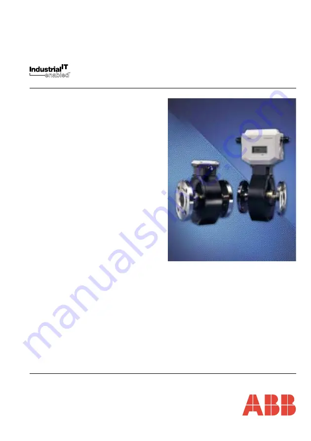
Electronic Commercial Water Meter

AquaMaster

TM

Installation Manual

IM/AM_9

Summary of Contents for AquaMaster IM9

Page 1: ...FieldIT Electronic Commercial Water Meter AquaMasterTM Installation Manual IM AM_9 ...

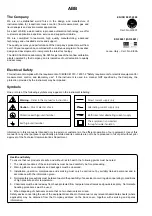
Page 2: ...utions must be taken to avoid the possibility of an accident occurring when operating in conditions of high pressure and or temperature 5 Chemicals must be stored away from heat protected from temperature extremes and powders kept dry Normal safe handling procedures must be used 6 When disposing of chemicals ensure that no two chemicals are mixed Safety advice concerning the use of the equipment d...

Page 3: ...llation Conditions 2 2 3 Transmitter Dimensions 4 2 4 GSM equipped Transmitters 5 2 4 1 GSM Antenna Installation 5 2 4 2 Connecting a Remote Antenna 6 2 4 3 Installing a SIM Card 7 3 ELECTRICAL INSTALLATION 8 3 1 Bonding Grounding 8 3 2 Connections 13 3 2 1 Sensor Terminal Box Connections Remote Versions only 13 3 2 2 Environmental Protection 13 3 2 3 Transmitter Connections 14 3 3 Input Output Co...

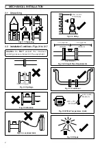
Page 4: ...er AquaMaster 2 MECHANICAL INSTALLATION 2 1 Unpacking 2 2 InstallationConditions Figs 2 1to2 17 Caution Do NOT exceed the maximum working pressure marked on the equipment Fig 2 1 Unpacking Fig 2 2 Spillage Fig 2 3 Vibration Fig 2 4 Localized Heat Fig 2 5 Siting Fig 2 6 Straight Pipe Requirements Fig 2 7 Fluid Level Fig 2 8 Within Temperature Limits Fig 2 9 Shade ...

Page 5: ...t gaskets Gasket same size as pipe 0 7 m minimum For access to batteries display and communication connector AquaMaster AquaMaster 2 MECHANICAL INSTALLATION Fig 2 10 Above Ground Fig 2 11 Temperature Difference Fig 2 12 Within Environmental Rating Fig 2 13 Underground Fig 2 14 Cable Routing Fig 2 15 Gasket Fitting Fig 2 16 Separation of Sensors Fig 2 17 Access to Transmitter ...

Page 6: ...17 7 preferred Allowance for cable bend each side 130 5 1 standard 230 9 armored 155mm 6 1 146 5 75 125 4 9 170 6 7 ø6 5 1 4 ø13 1 2 ø6 5 1 4 150 5 9 AquaMaster 2 MECHANICAL INSTALLATION 2 3 Transmitter Dimensions Fig 2 18 Fig 2 18 Transmitter Dimensions 50mm 50mm Remote Antenna Integral Antenna Fig 2 19 GSM Antenna Installation ...

Page 7: ... and logger download services a minimum of two visible signal strength indicator bars are recommended For SMS text a minimum of one visible signal strength indicator bar is recommended The following must also be observed when deciding on the antenna mounting location For best results mount the antenna as high above local ground level as possible If the antenna must be mounted below ground achieve ...

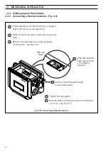
Page 8: ...t from the case using plain water Remove the transmitter top cover and battery mounting tray see Fig 3 12 3 Pass the antenna cable through a spare cable gland 4 5 6 Tighten the cable gland Refit the battery mounting tray and the transmitter top cover see Fig 3 12 7 2 MECHANICAL INSTALLATION 2 4 GSM equipped Transmitters 2 4 2 Connecting a Remote Antenna Fig 2 21 Fig 2 21 Connecting a Remote Antenn...

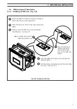
Page 9: ...battery mounting tray see Fig 3 12 3 4 6 Close the SIM card holder cover and slide into locked position Refit the battery mounting tray and the transmitter top cover see Fig 3 12 7 Slide to unlock and open the SIM card holder cover 5 Insert the SIM card contact side down and bevelled edge first into the SIM card holder Fig 2 22 Installing a SIM Card 2 4 GSM equipped Transmitters 2 4 3 Installing a...

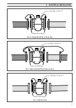
Page 10: ... spike For bonding connections use 4mm2 10AWG cable Sensors 80mm do not require grounding rings Connect the transmitter ground connection to the flowmeter body ground see Figs 3 6 and 3 7 Fig 3 1 All Metal Pipe Including Lined Metal Pipe Fluid Contact Rings See Figs 3 6 and 3 7 Key for Figs 3 1 to 3 9 Metal Pipes Plastic Pipes Fluid Contact Rings See Figs 3 6 and 3 7 Insulation Fig 3 2 Metal Pipe ...

Page 11: ... 6 and 3 7 Fluid Contact Rings See Figs 3 6 and 3 7 Fluid Contact Rings See Figs 3 6 and 3 7 Fig 3 3 Flanged Metal Pipe to Plastic Pipe Fig 3 5 All Plastic Pipe 3 ELECTRICAL INSTALLATION Fig 3 4 Metal Pipe With Plastic Make Up Insert ...

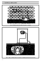
Page 12: ...10 3 ELECTRICAL INSTALLATION Fig 3 6 Battery Powered Transmitter Mounted in a Chamber Fig 3 7 Mains or Battery Powered Transmitter in Roadside Cabinet with Local Ground ...

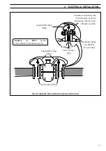
Page 13: ...ing wire not included Must be adequately rated to carry cathodic currents Gasket Gasket Supplied Bonding Cable Fluid Contact Ring Supplied Bonding Cables 3 ELECTRICAL INSTALLATION Caution Do NOT ground Cathodically Protected Systems Fig 3 8 Pipelines With Cathodic Protection DN 100mm ...

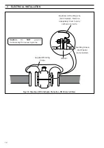
Page 14: ...ted connecting wire not included Must be adequately rated to carry cathodic currents Gasket Supplied Bonding Cable 3 ELECTRICAL INSTALLATION Caution Do NOT ground Cathodically Protected Systems Fig 3 9 Pipelines With Cathodic Protection DN 40mm to 80mm ...

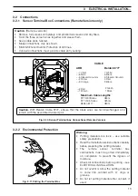
Page 15: ...material The remote sensor terminal box connections must be potted immediately on completion to prevent the ingress of moisture Check all connections before potting see ELECTRICAL INSTALLATION Do not overfill or allow the potting material to come into contact with O rings or grooves Do not let potting material enter conduit if used Fig 3 11 Potting the Terminal Box Caution With Belden Cable 8777 e...

Page 16: ...nded that cable glands are tightened finger tight initially then a further 1 2 to 3 4 turn applied using a suitable spanner Ensure that O ring seals and mating surfaces are clean to maintain environmental rating For IP68 protection where the transmitter could be submerged the termination area must be potted see Section 3 3 9 Slacken captive screws Lift off Cover 1 2 Remove battery tray 3 Press and...

Page 17: ...ic foil screens and any fillers Twist the three screen wires together and sleeve them Keep cable pairs twisted Make connections only as shown Maintain Environmental Protection at all times Conduit connections must provide cable entry sealing Fig 3 13 Transmitter Connections Glands Conduit Entry ...

Page 18: ...Red RD 3 Orange OR 4 Yellow YL 5 Sleeved Ground 6 Blue BL 7 Violet VI ABB Belden 8777 CABLE 1 Black 2 Green 3 Black 4 Red 5 Sleeved Ground 6 Black 7 White Fig 3 14 Sensor Cable Connections Gland Conduit Remote version Caution With Belden Cable 8777 ensure that the black wires are not interchanged and remain with the associated twisted pair ...

Page 19: ...ems is to wire COM to 0V 3 3 1 Frequency Outputs Fig 3 16 Fig 3 16 Frequency Output Connections Fig 3 17 Alarm Output Connections Note Outputs 1 2 are not polarity sensitive The common connection for these outputs is designated COM Note Output 3 is not polarity sensitive The common connection for these outputs is designated COM Alarm functions are available only with product software versions 1 1 ...

Page 20: ...O E 3 P O t u p t u O m r a l A d e R e t i h W F 2 P O r o t a c i d n I n o i t c e r i D r o s e s l u P e s r e v e R e u l B G m o C P O n o m m o C n i a r D S e r i W n e e r c H d e v r e s e R J d n G P I n o m m o C t u p n I e t i h W K P I t u p n I t c a t n o C t e l o i V L D X R n o i t c e n n o c t u p n i l a i r e s a t a d e v i e c e R e s i o u q r u T M D X T n o i t c e n ...

Page 21: ...ich convert forward and reverse pulses into a single pulse line with a direction signal Such leads will NOT work with AquaMaster and are unnecessary as AquaMaster directly provides the correct signals for these loggers 2 Wire Pad Connection 1 5 m to 40 m Recommended Cable ABB STT4009 or equivalent Data 0V 3 Wire Transponder Connection Data 0V Transponder V 3 terminal PCB WADX2026 Reading Pad Cable...

Page 22: ... Connection Fig 3 21 Fig 3 21 Local Computer Connections ABB Limited Part No WEBC2000 Connected to 9 pin Serial Data socket on PDA or PC via Laplink lead adaptor 9 pin male for link lead to Psion 9 pin female direct to PC Original Style Current Style ...

Page 23: ...R I R 9 2 2 C N C N D N G D N G 5 7 D N G 5 7 s e l b a c k n i L C P A D P h t i w s e t a m o s l A 3 3 7 Remote Computer Connection Fig 3 22 This interface operates only with external power applied to the transmitter Fig 3 22 RS232 Connections Current Design RTS RXD TXD GND RI CTS Early Design see Note below RTS RXD TXD GND RI CTS AquaMaster Transmitter Connector Block Layout Modem Radio Modem ...

Page 24: ...ly connections earthing arrangements are identical for cathodically protected remote transmitter systems For cathodically protected integral transmitter systems follow cathodic installation practices Fig 3 23 Power Supply Connections Internal External Transmitter End View 4mm2 10 A W G Copper Wire ABB Limited METER CODE LOG CODE TAG SERIAL SUPPLY 95V 240VAC 15VA BatteryBackup ENCLOSURE 6P IP68 Mad...

Page 25: ...aterial Caution For IP68 protection against water ingress pot the termination area on the metal transmitter versions Check all connections and operations before potting see ELECTRICAL INSTALLATION Do not overfill or allow the potting material to come into contact with O rings or grooves allow for inserting battery tray Do not let potting material enter conduit s if used Insert battery tray into po...

Page 26: ...e from the same side of the termination area as the battery position 4 1 Connecting Batteries The AquaMaster is supplied with one or two batteries but not connected To connect see Fig 4 1 Note GSM equipped transmitters are supplied with the batteries connected but in transportation mode refer to the label attached to the equipment 4 2 Start up Remove any plastic film from the AquaMaster light sens...

Page 27: ...ver and ensure the screws are tightened fully 1 Remove the top cover of the transmitter see Fig 3 12 2 Slide out the connector from behind the battery clip 3 Connect the battery or batteries to the wire connector s inside the top of the transmitter unit 4 Ensure that the end of the battery with the connection wires is pushed up against the inside end of the top cover 5 Push the connection centrall...

Page 28: ...oving the covering the display activates and cycles through the programmed set of display measurements With external AC power applied the display is permanently active Information For the use of local or remote serial communication and how to alter the displayed set of measurements or instrument setup see the Quick Reference Programming Guide 4 4 Replacing a Battery Fig 4 3 Note Each battery must ...

Page 29: ...ng the new battery DO NOT change a battery if its associated icon is flashing Replace Both Batteries Important If both batteries require replacement first change the cell indicated by the steady icon in this example the left battery The flashing icon indicates the battery currently in use 4 4 1 Spares Kits Transmitter Current Model flat cover version Battery Kit comprises 1 battery and one seal ME...

Page 30: ...m the case using plain water Remove the top cover of the transmitter see Fig 3 12 to expose the batteries 3 4 Unclip the appropriate battery from the tray and disconnect the lead at the connector dispose of the battery in the approved manner 5 Fit a new battery from the battery kit into the clips Clean the O ring mating surface around the opening into the transmitter body using a wet tissue 6 7 8 ...

Page 31: ...he cover 3 Wipe the O ring mating area around the opening into the transmitter body with a wet tissue 4 Slide out the connector from behind the battery clip of the battery to be replaced and pull apart Remove the battery and dispose of it in the approved manner 6 Slide out the other connector from behind the battery clip and unclip the remaining battery but do not disconnect it Repeat step using t...

Page 32: ...inadvertently The operation of wireless appliances in an aircraft is forbidden to prevent interference with communications systems Failure to observe these instructions may lead to the suspension or denial of cellular services to the offender legal action or both 3 Do not operate the cellular terminal or mobile in the presence of flammable gases or fumes Switch off the cellular terminal when you a...

Page 33: ...stem 1 2 3 4 6 7 5 Optional Power Supply Pulse Alarm Circuits Common Processor 1 2 3 4 6 7 5 Local Configuration Adaptor Part No WEBC2000 Optional RS232 Communication Port Optional GSM Modem Pressure Transducer APPENDIX B AQUAMASTER BLOCK DIAGRAM ...

Page 34: ... 6 0 0 5 1 0 9 9 5 2 2 5 7 2 3 6 0 1 1 5 2 0 0 6 4 2 0 1 0 2 2 0 0 0 5 0 1 0 1 1 0 0 5 2 0 5 6 1 5 7 3 7 4 3 9 7 9 3 1 2 3 AC powered Meters Flow Requirements per ISO 4064 Standard Version e z i S Q x a m N Q 5 2 0 Qt Q n i m m m n i m3 n i m l a g U h m3 n i m l a g U h m3 n i m l a g U h m3 n i m l a g U h m3 n i m l a g U h 5 1 5 0 3 1 3 7 5 1 3 3 0 5 7 0 0 4 4 0 0 0 1 0 0 8 1 0 0 4 0 0 0 0 2 5...

Page 35: ...9 1 3 9 1 4 4 7 7 8 1 0 0 2 0 0 5 0 2 0 1 0 2 2 0 0 0 5 0 1 6 7 1 0 0 0 4 0 9 9 5 2 2 5 7 2 3 6 0 1 1 5 2 0 6 1 0 0 6 4 2 0 7 6 4 3 5 7 8 7 0 4 7 7 2 0 0 3 6 0 5 6 1 5 7 3 7 4 3 9 7 9 3 1 2 3 0 0 2 e z i S Q4 Q3 Q 5 2 0 Q2 Q1 R m m n i m3 n i m l a g U h m3 n i m l a g U h m3 n i m l a g U h m3 n i m l a g U h m3 n i m l a g U h 5 1 5 0 2 2 5 8 1 4 3 3 0 5 7 0 0 4 4 0 0 0 1 0 0 8 1 0 0 4 0 0 0 0 0...

Page 36: ... 0 1 0 0 5 5 0 5 2 1 0 0 4 4 0 0 0 1 0 1 1 5 2 4 4 0 1 0 0 1 0 0 3 2 1 0 1 8 8 0 0 0 2 0 4 0 7 0 0 6 1 6 7 1 0 4 0 7 6 1 0 0 1 e z i S Q x a m N Qt Q n i m m m n i m3 n i m l a g U h m3 n i m l a g U h m3 n i m l a g U h m3 n i m l a g U h 0 5 2 2 3 1 0 3 6 6 5 1 2 3 1 3 0 2 5 4 0 5 6 5 2 0 2 2 0 5 0 1 1 5 2 2 2 5 3 3 5 7 0 0 8 3 8 5 3 0 8 6 7 1 0 4 5 3 8 3 5 2 1 0 0 1 4 8 2 5 0 2 1 4 6 2 0 6 3 5 ...

Page 37: ... standard SWA cable available on application Power supply Battery life 0 to 50 C 32 to 122 F 1 battery typically 1 2 years 2 batteries typically 3 years extended life is possible to give say 5 years for two cells with a small degradation in response time and slightly increased measurement uncertainty contact ABB for details Battery life is shorter with GSM depending on how frequently it is used an...

Page 38: ...nection Standard quick fit male probe MIL style connector Operating temperature range 20 to 70 C 4 to 158 F Accuracy typical 0 4 of range Thermal error band typically 100 C 212 F 1 5 span Cable length 1 5 10 or 20m 3 16 32 or 65 ft Logger details r e g g o L 1 2 3 n o i t c n u F r e g g o L w o l F e r u s s e r P w o l F e r u s s e r P d r a w r o F e s r e v e R s f f i r a T w o l F t e N s l...

Page 39: ...P e g u a G e g u a G e t a R w o l F y a l p s i D s e Y s e Y l a t o T d r a w r o F y a l p s i D s e Y s e Y l a t o T e s r e v e R y a l p s i D s e Y s e Y l a t o T t e N y a l p s i D o N o N e r u s s e r P y a l p s i D x T e r u s s e r P h t i w d e r e d r o f i s e Y x T e r u s s e r P h t i w d e r e d r o f i s e Y e t a D y a l p s i D o N o N y t i c o l e V y a l p s i D o N ...

Page 40: ... 7 1 9 7 0 0 2 0 1 3 2 5 6 5 2 6 8 9 1 2 9 7 0 0 2 8 1 0 4 0 8 3 6 8 9 1 2 9 7 0 0 2 8 1 0 4 0 0 1 4 8 9 5 0 3 2 8 9 0 5 2 4 2 4 5 0 5 1 6 8 1 1 1 8 2 8 1 1 0 0 3 8 3 4 8 0 0 2 8 8 5 1 2 0 4 8 3 1 0 5 3 7 3 1 8 0 5 2 0 1 3 7 1 0 4 4 7 7 1 0 5 4 0 6 2 3 1 0 0 3 2 1 9 8 1 0 8 4 7 9 1 0 0 5 0 7 4 5 1 e z i S r e t e M n i m m s n o i s n e m i D t h g i e W x o r p p A m m n i A B C g k b l 0 5 3 4 1...

Page 41: ...39 NOTES ...

Page 42: ...40 NOTES ...

Page 43: ... pH conductivity and dissolved oxygen transmitters and sensors ammonia nitrate phosphate silica sodium chloride fluoride dissolved oxygen and hydrazine analyzers Zirconia oxygen analyzers katharometers hydrogen purity and purge gas monitors thermal conductivity Customer Support We provide a comprehensive after sales service via a Worldwide Service Organization Contact one of the following offices ...

Page 44: ...ed herein without notice ABB 2004 Printed in UK 08 04 ABB Inc 125 E County Line Road Warminster PA 18974 USA Tel 1 215 674 6000 Fax 1 215 674 7183 ABB Limited Oldends Lane Stonehouse Gloucestershire GL10 3TA UK Tel 44 0 1453 826661 Fax 44 0 1453 829671 ABB has Sales Customer Support expertise in over 100 countries worldwide www abb com ...

Reviews: