3.2.5
X4 connector
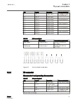
Table 16:
X4 connector pinout
PIN
Symbol
Description
1
LOADCUT_A
Load control relay out, normal
closed (NC)
2
LOADCUT_B
Load control relay out, normal
closed (NC)
3
AI1_A
Analog In 1, -5 V...+5 V
measurement, ±300 mV
(-10...+55°C, 0 V...+5 V), Hall-
sensor
1)
4
AI1_B
Analog In 1, -5 V...+5 V
measurement, ±300 mV
(-10...+55°C, 0 V...+5 V), Hall-
sensor
1)
5
TESTLOAD_A
Relay out, test load for battery
test case
6
TESTLOAD_B
Relay out, test load for battery
test case
7
HTR_A
Heater/Extra relay
8
HTR_B
Heater/Extra relay
9
AI2_A
Analog In 2, -5 V...+5 V
measurement, ±300 mV
(-10...+55°C, 0 V...+5 V), Hall-
sensor
1)
10
AI2_B
Analog In 2, -5 V...+5 V
measurement, ±300 mV
(-10...+55°C, 0 V...+5 V), Hall-
sensor
1)
11
DIC_5
Common supply voltage for
DI16, DI17
12
DI16
Digital input 16
13
DI17
Digital input 17
14
DO7_A
Relay output 7
15
DO7_B
Relay output 7
1) Can be used as a 4...20 mA input using external resistor
Table 17:
X4 connector types
Connector
Manufacturer
Connector type (part number)
Panel header
Phoenix Contact
MSTBV 2.5/15-GF-5.08
(1777206)
Matching plug
Phoenix Contact
MSTB 2.5/15-STF-5.08
(1778111)
1MRS758459 C
Section 3
Physical connections
ARC600
23
User Manual

