25
1SDH000759R0002, L4106
Installation and operating instructions, ATS021
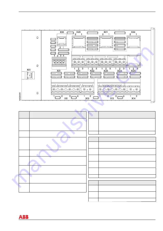
Connectors, ATS021
Table 6.1
Connectors / Outputs / Inputs
6. Connecting
Figure 6.4
Connectors, ATS021
Con-
nector
Description
X11:1
X11:2
X11:3
X11:4
Normal line LN1: L1
Normal line LN1: L2
Normal line LN1: L3
Normal line LN1: N
X13:1
X13:2
Normal line (power supply): L
Normal line (power supply): N
X12:1
X12:2
X12:3
X12:4
Emergency line LN2: L1
Emergency line LN2: L2
Emergency line LN2: L3
Emergency line LN2: N
X14:1
X14:2
Emergency line (power supply): L
Emergency line (power supply): N
X21:1
Common
X21:2
DO1
X21:3
DO2
X22:1
Common
X22:2
DO3
X22:3
DO4
X23:1
DO5 start
X23:2
Common
X23:3
DO5 stop
X24:1
DO6 ok
X24:2
Common
X24:3
DO6 alarm
Con-
nector
Description
X31:1
X31:2
X31:3
X31:4
DI3
DI1
DI2
DI supply
X61
Equipment earth
Output Description
D01
Output to open the protection device of the
normal line (normal open)
D02
Output to close the protection device of the
normal line (normal open)
D03
Output to open the protection device of the
emergency line (normal open) (only breaker)
D04
Output to close the protection device of the
emergency line (normal open) (only breaker)
D05
Output to control the startup of the generator
(exchange)
D06
Signaling emergency / alarm (exchange)
Input
Description
DI1
Protection device on normal line status input (0
open, 1 close)
DI2
Protection device on emergency line status
input (0 open, 1 close)
DI3
Logic enable/disable


