background image

AX400 Series

User Guide

Models AX460 and AX466
Single and Dual Input pH/Redox
(ORP) Analyzers

7.00

Monitoring pH

7.00

pH

pH

7.00

Monitoring pH

7.00

pH

pH

Summary of Contents for AX400 Series

Page 1: ...AX400 Series User Guide Models AX460 and AX466 Single and Dual Input pH Redox ORP Analyzers 7 00 Monitoring pH 7 00 pH pH 7 00 Monitoring pH 7 00 pH pH ...

Page 2: ... conditions result in degraded process system performance leading to personal injury or death Therefore comply fully with all Warning and Caution notices Information in this manual is intended only to assist our customers in the efficient operation of our equipment Use of this manual for any other purpose is specifically prohibited and its contents are not to be reproduced in full or part without ...

Page 3: ...Configure Display 26 5 3 Configure Sensors 27 5 4 Configure Alarms 30 5 4 1 Wash Cycle Configuration Applicable Only to Alarm 3 32 5 5 Configure Outputs 34 5 6 Configure Clock 36 5 7 Configure Security 37 5 8 Configure Logbook 37 5 9 Test Outputs and Maintenance 38 Section Page 6 INSTALLATION 39 6 1 Siting Requirements 39 6 2 Mounting 40 6 2 1 Wall Pipe mount Analyzers 40 6 2 2 Panel mount Analyze...

Page 4: ...l an external power supply to a solenoid or pump and the frequency duration and recovery time for the wash cycle are also programmable During a wash cycle the analog output value is held in its pre cycle condition Analyzer operation and programming are performed using five tactile membrane keys on the front panel Programmed functions are protected from unauthorized alteration by a four digit secur...

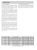
Page 5: ...just Parameter X Y Z Select New value is automatically stored Menu 1 Menu 2 Advance to next menu 2 1 Powering Up the Analyzer Caution Ensure all connections are made correctly especially to the earth stud see Section 6 3 1 Ensure the input sensor s is are connected correctly 2 Switch on the power supply to the analyzer A start up screen is displayed while internal checks are performed then the Ope...

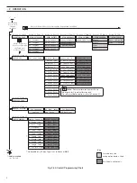
Page 6: ...GE Section 2 3 Page 6 Section 3 1 Page 12 Section 3 2 Page 13 Section 3 3 Page 13 Section 3 4 Page 14 Section 3 5 Page 14 Section 4 1 Page 18 Section 5 1 Page 25 Section 5 2 Page 26 Section 5 3 Page 27 Section 3 6 Page 17 Set Auto Buffers Buffer Type Set Buffer 1 Set Buffer 2 A Slope Check Sensor Cal B B Buffer Method B Immerse Buf 1 B Cal Buffer 1 B Immerse Buf 2 B Cal Buffer 2 B Calibration B Sl...

Page 7: ...onfig Output 3 AO3 Assign AO3 Range AO3 Span Value AO3 Zero Value AO3 Default AO3 Default Val Test Output 3 Test Output 4 Use the Sidescroll Key to scroll through the Pages within each Menu Section 5 4 Page 30 Section 5 5 Page 34 Section 5 7 Page 37 Section 5 9 Page 38 Use the Menu Key to scroll through the Menus Use the Downscroll Key to scroll through the Parameters within each Page CONFIG CLOCK...

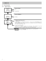
Page 8: ...e these limits check the electrode system pH check value zero point Displayed as an additional indication of pH electrode system condition 7pH is the optimum value for glass electrodes and 0pH for Antimony electrodes Alarm 3 set to Wash A3 Type Section 5 4 see Section 2 3 3 Alarm 3 not set to Wash 2 3 Operating Page 2 3 1 Single Input pH 2 OPERATION Monitoring pH 7 00pH 24 4Deg C Wash Function Mon...

Page 9: ...um slope value see Set Min Slope in the CONFIG SENSORS page Section 5 3 and 105 is displayed If the value is outside these limits check the electrode system pH check value zero point Displayed as an additional indication of pH electrode system condition 7pH being the optimum value for glass electrodes and 0pH for Antimony electrodes Sensor B Slope and pH Check Value slope value See Sensor A above ...

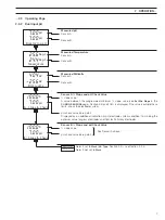
Page 10: ...sor calibration enabled Section 5 3 see Section 4 1 Alter Sec Code not set to zero Section 5 7 see Section 5 1 Alter Sec Code set to zero Section 5 7 see Section 5 2 Wash Function set to Manual see below Wash Function not set to Manual Press to Wash Manual Wash only Press to Wash and Press to Abort are shown alternately on the lower display line Press the key to initiate the wash cycle The display...

Page 11: ...SENSORS page see Section 5 3 the lower display line shows Monitoring ORP Sensor A Offset Displays the offset value for the sensor set in A Adjust Offset see Section 4 1 3 Alarm 3 set to Wash A3 Type Section 5 4 see Section 2 3 3 Alarm 3 not set to Wash Monitoring Redox 404mV 25 6Deg C A mV Offset 0mV Wash Function Dual Redox 2 OPERATION ...

Page 12: ...t to None in the CONFIG SENSORS page see Section 5 3 Sensor A Offset Displays the offset value for Sensor A set in A Adjust Offset see Section 4 1 3 Sensor B Offset Displays the offset value for Sensor B set in B Adjust Offset see Section 4 1 3 Alarm 3 set to Wash A3 Type Section 5 4 see Section 2 3 3 Alarm 3 not set to Wash 2 3 Operating Page 2 3 5 Dual Input Redox ORP 2 OPERATION Dual Redox 404m...

Page 13: ... Sensor A Sensor B Sensor B Offset Displays the offset value for Sensor B set in B Adjust Offset see Section 4 1 3 Sensor A Slope and pH Check Value slope value A value between the programmed minimum slope value see Set Min Slope in the CONFIG SENSORS page Section 5 3 and 105 is displayed If the value is outside these limits check the electrode system pH check value zero value Displayed as an addi...

Page 14: ...int Note Alarm 5 is available only if the optional analog output board is fitted Return to main menu Sensor calibration enabled Section 5 3 see Section 4 1 Alter Sec Code not set to zero Section 5 7 see Section 5 1 Alter Sec Code set to zero Section 5 7 see Section 5 2 8 30pH A1 Setpoint Sen A Temp A VIEW SETPOINTS 35 0Deg C A2 Setpoint Sen B 6 80 A3 Setpoint Temp B 55 0Deg C A4 Setpoint Off A5 Se...

Page 15: ... outputs 3 and 4 if optional analog output board fitted 3 3 View Hardware Sensor A Module Shows the type of input board fitted to the analyzer for the Sensor A input Sensor B Module Dual input analyzers only Shows the type of input board fitted to the analyzer for the Sensor B input Option Board Shows the type of option board fitted to the analyzer if applicable See Section 3 4 Sensor calibration ...

Page 16: ...es entry 1 is the most recent each comprising an alarm number alarm state On or Off and the date and time of the occurrence Optional analog input board fitted see Section 3 6 Sensor calibration enabled Section 5 3 see Section 4 1 Alter Sec Code not set to zero Section 5 7 see Section 5 1 Alter Sec Code set to zero Section 5 7 see Section 5 2 Advance to entries 2 to 10 Note If no more entries are s...

Page 17: ...s View Logbook Use the and keys to access the Power logbook Power The Power logbook contains up to 2 entries entry 1 is the most recent each comprising the power state On or Off and the date and time of the occurrence Optional analog input board fitted see Section 3 6 Sensor calibration enabled Section 5 3 see Section 4 1 Alter Sec Code not set to zero Section 5 7 see Section 5 1 Alter Sec Code se...

Page 18: ...d the date and time of the occurrence Optional analog input board fitted see Section 3 6 Sensor calibration enabled Section 5 3 see Section 4 1 Alter Sec Code not set to zero Section 5 7 see Section 5 1 Alter Sec Code set to zero Section 5 7 see Section 5 2 Advance to entries 2 to 5 Note If no more entries are stored the display shows No More Entries VIEW CLOCK Calibration VIEW LOGBOOK 1 Sen A Pas...

Page 19: ...4 1 Alter Sec Code not set to zero Section 5 7 see Section 5 1 Alter Sec Code set to zero Section 5 7 see Section 5 2 3 6 View Clock Note The VIEW CLOCK function is available only if the optional analog output board is fitted 3 OPERATOR VIEWS Date 01 01 01 VIEW CLOCK Time 12 00 Monitoring pH SENSOR CAL Security Code CONFIG DISPLAY VIEW CLOCK ...

Page 20: ...n 5 7 Probe Type set to pH for either sensor if dual input analyzer continued below Probe Type set to Redox or ORP for both sensors if dual input analyzer continued on page 21 Set Auto Buffers Continued on Page 21 Alter Sec Code not set to zero Section 5 7 see Section 5 1 Alter Sec Code set to zero Section 5 7 see Section 5 2 Continued below Buffer Type Select the relevant type of buffer solution ...

Page 21: ... of the buffer 2 solution Note The solution selected for buffer 2 must be at least 2pH value greater than that selected for buffer 1 e g if buffer 1 is set to 7pH buffer 2 must be set to at least 9pH Set Buffer 1 Set Buffer 2 9 18pH Set Auto Buffers 4 O1pH 4 1 Sensor Calibration 4 1 1 Set Buffer Type pH Only 4 SETUP ...

Page 22: ...t for the previous point The setting may be increased but not decreased Solution B Enter point 1 to 5 Solution B set up is identical to solution A set up Note For accurate calibration it is important to repeat the above for buffer solution B at all 5 points along the pH temperature curve The analyzer calculates the pH temperature relationship from the data entered See Section 4 1 3 Alter Sec Code ...

Page 23: ...o pH see Section 4 1 4 Adjust Offset ORP Redox probes only mV and Adjust are shown alternately on the upper display line Use the and keys to adjust the upper display line to the required offset value for the process Return to main menu Alter Sec Code not set to zero Section 5 7 see Section 5 1 Alter Sec Code set to zero Section 5 7 see Section 5 2 Return to top of page 4 1 Sensor Calibration 4 1 3...

Page 24: ...asheet provided with the solution Press the key to initiate calibration Note To abort calibration press the key again at any time before calibration is complete see below The center display line shows the sensor e m f As calibration procedes a progress indicator appears in the lower display line When a stable e m f is detected the lower display line shows 100 The display then changes for 2 seconds...

Page 25: ...ibration Messages Calibrate Buffer 2 Two Point Calibration only Immerse Sensor A in the second buffer solution and continue as for Buffer 1 Note To abort calibration press the key again at any time before calibration is complete see previous page The center display line shows the sensor e m f As calibration procedes a progress indicator appears in the lower display line When a stable e m f is dete...

Page 26: ...ode not set to zero Section 5 7 see Section 5 1 Alter Sec Code set to zero Section 5 7 see Section 5 2 Continued below Slope Value slope value The value between the programmed minimum slope value see Set Min Slope in the CONFIG SENSORS page Section 5 3 and 105 generated during the last valid two point calibration is displayed pH check value The value generated during the last valid two point calib...

Page 27: ...eters If an incorrect value is entered access to subsequent programming pages is prevented and the display reverts to the Operating Page see Section 2 3 Note This item is displayed only if Alter Sec Code is not set to zero see Section 5 7 See Section 5 2 5 1 Security Code Security Code 0000 CONFIG DISPLAY ...

Page 28: ...Up Display Backlight Backlight Use the and keys to select the required backlight option Auto Backlight comes on at each button press and switches off one minute after the last button press On Backlight is always on Return to main menu See Section 5 3 CONFIG DISPLAY Set Language Temp Units Off Set Temp Units Deg F Deg C LED Backlight Set Backlight Auto On CONFIG DISPLAY CONFIG SENSORS Set Backlight...

Page 29: ...pe of input selected Standard or Differential see Fig 6 9 wall pipe mount analyzers or Fig 6 11 panel mount analyzers Probe Type set to Redox or ORP continued below Probe Type set to pH continued on next page Temperature Sensor Select the type of temperature sensor used Pt100 Pt1000 Balco 3K or None Enable Calibration Select Yes to enable sensor calibration Select No to disable sensor calibration ...

Page 30: ... Automatic Temperature Compensation only Select the type of temperature sensor used Pt100 Pt1000 or Balco 3K continued on next page Preset Temperature Manual Temperature Compensation only Enter the temperature of the sample within the range 10 0 to 120 0 C continued on next page A Temp Comp Manual Auto pH A Electrode Antim Glass A Temp Sensor 3K Bal Pt1000 Pt100 A Preset Temp Deg C 25 0 A Sample C...

Page 31: ...lications enter 0 035 pH Calibration Minimum Slope Value Set the required pH calibration minimum slope value in within the range 60 0 to 90 0 in 0 1 increments The calibration fail limit is set automatically to 20 below the minimum slope setting see table 4 1 Sensor B dual input analyzers only configuration is identical to Sensor A configuration See Section 5 4 5 PROGRAMMING Config Sensor B Config...

Page 32: ...r a condition that causes any of the error messages in Table 8 1 to be displayed Wash Alarm 3 is configured to control the wash sequence Note The Wash alarm type can be assigned only to Alarm 3 and is displayed only when the lower display line shows A3 Type A1 Type set to Off or Status A1 Type set to Alarm continued below A3 Type set to Wash see Section 5 4 1 Alarm 1 Assign The alarm can be assign...

Page 33: ...ifferential set point can be defined between 0 and 5 of the alarm set point value Set the required hysteresis in 0 1 increments See also Figs 5 2 to 5 6 Alarm 1 Delay When an alarm condition occurs the activation of the relays and LEDs can be delayed for a specified time period If the alarm clears within the period the alarm is not activated Set the required delay in the range 0 to 60 seconds in 1...

Page 34: ... Wash duration is set in 15 second intervals between 15 and 45 seconds then in 1 minute intervals between 1 and 10 minutes Recovery Period The recovery period is set in 0 5 minute intervals between 0 5 and 5 0 minutes Configure Alarm 4 See Section 5 5 Wash Frequency Hours Mins Wash Duration 15 Recovery Period 1 0Mins 15 CONFIG OUTPUTS Config Alarm 4 Config Alarm 3 A3 Type set to Wash Wash Mode Con...

Page 35: ...y but no Hysteresis 5 4 Configure Alarms Relay Energized LED Off Relay De energized LED On Process Variable High Set Point Relay Energized LED Off Relay De energized LED On Process Variable High Set Point Delay Hysteresis Relay Energized LED Off Relay De energized LED On Process Variable Hysteresis High Set Point Relay Energized LED Off Relay De energized LED On Process Variable High Set Point Del...

Page 36: ... Adjust are shown alternately on the upper display line Use the and keys to adjust the displayed reading to the required span value Note The minimum and maximum span values are determined by the Zero Value setting see next page plus the minimum differential e g to set a Span Value of 0 00 pH first set the Zero Value to 2 00pH pH 0 00 to 16 00 pH minimum differential 2 00pH Redox ORP 1100 to 1200 m...

Page 37: ...old the analog output at the value prior to the failure On Stop on failure This drives the analog output to the level set in the Default Val frame below Off Ignore failure and continue operation Output 2 configuration Optional analog output board fitted see Section 5 6 Optional analog output board not fitted see Section 5 7 Default Output set to Hold or Off Default Output set to On continued below...

Page 38: ...date in the form dd mm yy Press to move between the day month and year fields Use the and keys to adjust each field Time Set the time in the form hh mm Press to move between hours and minute fields Use the and keys to adjust each field Press to Set and Press to Abort are shown alternately on the lower display line Press the appropriate key to set the clock or abort the changes Set Clock Date 01 01...

Page 39: ...main menu See Section 5 8 5 7 Configure Security 5 8 Configure Logbook Configure Logbook Use the and keys to to set the logbook On or Off If Off is selected all data entries in the logbook are cleared Return to main menu See Section 5 9 Logbook CONFIG LOGBOOK TEST MAINTENANCE CONFIG LOGBOOK Off On Alter Sec Code 0000 Alter Cal Code 0000 CONFIG SECURITY CONFIG LOGBOOK CONFIG SECURITY Alter Sec Code...

Page 40: ...eoretical output current value to give the output required See Section 7 3 Test remaining outputs Maintenance Hold Outputs Enables the relay action and analog outputs to be maintained Auto Hold is released automatically after six hours On Changes in relay action and analog outputs are inhibited Off Changes in relay action and analog outputs are not inhibited Note The LEDs flash while the analyzer ...

Page 41: ...tion It is preferable to mount the analyzer at eye level allowing an unrestricted view of the front panel displays and controls Fig 6 1 Siting Requirements C Within Environmental Limits B Within Temperature Limits A Maximum Distance Between Analyzer and Electrode Electrode Maximum Distance 100m 275 ft 65 C Max 20 C Min IP66 NEMA 4X 6 INSTALLATION ...

Page 42: ...g Position U bolts on pipe Position plate over U bolts Secure transmitter to mounting plate Secure plate A Wall mounting Mark fixing centres see Fig 6 2 Drill suitable holes Secure instrument to wall using suitable fixings 1 2 3 4 1 2 3 61 23 8 OD Vertical or Horizontal Post Fig 6 3 Wall Pipe mounting 6 2 Mounting 6 2 1 Wall Pipe mount Analyzers Figs 6 2 and 6 3 ...

Page 43: ...in their slots Secure the analyzer by tightening the panel clamp retaining screws Loosen the retaining screw on each panel clamp Remove the panel clamp and anchors from the instrument case Cut a hole in the panel see Fig 6 4 for dimensions Instruments may be close stacked to DIN 43835 1 2 3 4 5 6 Fig 6 5 Panel mounting 6 2 Mounting 6 2 2 Panel mount Analyzers Figs 6 4 and 6 5 Caution The clamp mus...

Page 44: ...st the appropriate screw terminals and are short and direct Do not tuck excess cable into the terminal compartment Cable glands conduit fittings ensure that the NEMA4X IP66 rating is not compromised when using cable glands conduit fittings and blanking plugs bungs M20 holes The M20 glands accept cable of between 5 and 9mm 0 2 and 0 35 in diameter Relays the relay contacts are voltage free and must...

Page 45: ... the value of the resistor capacitor network depends on the load current and inductance that is switched Initially fit a 100R 0 022µF RC suppressor unit part no B9303 as shown in Fig 6 6A If the analyzer malfunctions locks up display goes blank resets etc the value of the RC network is too low for suppression and an alternative value must be used If the correct value cannot be obtained contact the...

Page 46: ...utside Secure the cable gland with the securing nut 2 3 4 6 Cable entry knockouts Factory fitted cable gland 1 Release the captive screws and remove the terminal cover plate Fig 6 7 Cable Entry Knockouts Wall Pipe mount Analyzer 6 3 Connections General 6 3 2 Cable Entry Knockouts Wall Pipe mount Analyzer Fig 6 7 The analyzer is supplied with 7 cable glands one fitted and six to be fitted as requir...

Page 47: ...ts and high common mode voltages are switched off 6 4 Wall Pipe mount Analyzer Connections 6 4 1 Access to Terminals Fig 6 8 Fig 6 8 Access to Terminals Wall Pipe mount Analyzer Release Captive Screws and Remove Terminal Cover Plate Terminal Block A Terminal Block B Terminal Block C Analog Option Board Case Earth Ground Stud ...

Page 48: ... When a 2 wire Pt100 Pt1000 or Balco 3K temperature compensator is fitted Solution Earth also referred to as Ground Rod TC Temperature Compensator Terminal Block B pH Redox ORP without solution earth standard input Sensor B Sensor A 1 9 TC Common Link 1 2 9 10 2 10 TC Third Lead 3 11 TC 4 12 N A 5 13 Reference Electrode 6 14 Screen 7 15 Not Used 8 16 Glass Metal Electrode TC Common Link 1 2 9 10 p...

Page 49: ...oltage operated control circuits and high common mode voltages are switched off 6 5 Panel mount Analyzer Connections 6 5 1 Access to Terminals Fig 6 10 Terminal Block C Analog Option Board Terminal Block B Terminal Block A Case Earth Ground Stud Fig 6 10 Access to Terminals Panel mount Analyzers ...

Page 50: ... TC B1 B2 B3 B4 B5 B6 B7 B8 B9 B10 B11 B12 B13 B14 B15 B16 Common Third Lead TC Temperature Compensator Connections Terminal Block B Sensor B Sensor A 1 9 2 10 3 11 4 12 5 13 6 14 7 15 8 16 TC Common Link 1 2 9 10 TC Common Link 1 2 9 10 pH Redox ORP without solution earth standard input pH Redox ORP with solution earth differential input TC Third Lead TC Third Lead TC N A TC Reference Electrode R...

Page 51: ...and disconnect the electrode system temperature compensator s and current output s from the analyzer s terminal blocks b Sensor A 1 Link terminals B9 and B10 2 Connect the millivolt source to terminals B16 ve and B14 ve to simulate the pH or Redox input Connect the millivolt source earth to the Case Earth Ground Stud see Fig 6 8 wall pipe mount analyzer or Fig 6 10 panel mount analyzer 4 Connect t...

Page 52: ...ave Config Factory Config User Config Alter Fact Code Cal Output 3 Cal Output 4 O3 Adjust 4mA O4 Adjust 4mA O3 Adjust 20mA O4 Adjust 20mA Press To Abort Press To Set Cal Output 2 O2 Adjust 4mA O2 Adjust 20mA Use the Sidescroll Key to scroll through the Pages within each Menu Use the Menu Key to scroll through the Menus Use the Downscroll Key to scroll through the Parameters within each Page Sectio...

Page 53: ...he upper 6 segment display shows the measured input voltage Once the signal is within range the lower 6 segment display shows the same value and Calib is displayed to indicate that calibration is in progress Millivolt Span Set the millivolt source to 1000mV The display advances automatically to the next step once a stable and valid value is recorded Temperature Zero 100R Set the temperature simula...

Page 54: ...d value is recorded Temperature Zero 2k0 Set the temperature simulator to 2000Ω The display advances automatically to the next step once a stable and valid value is recorded Temperature Span 5k0 Set the temperature simulator to 5000Ω The display returns automatically to Cal Sensor A once a stable and valid value is recorded 7 3 Factory Settings A T Span 5K0 A T Zero 2K0 0 416 0 416 Volts Calib 0 8...

Page 55: ... 5 5 does not affect the reading See below Operating Page see Section 2 3 Calibrate Output 2 Note Output 2 calibration and Outputs 3 and 4 if optional analog output board is fitted is identical to Output 1 calibration Optional analog output board fitted Optional analog output board not fitted continued on next page Optional analog output board fitted Optional analog output board not fitted continu...

Page 56: ...meters in the Configuration Pages to the Company Standard Save User Config saves the current configuration into memory Load User Config reads a saved user configuration into memory User Config and Factory Config are displayed alternately if a User Configuration has been saved previously Use the and keys to make the required selection Note User Config is displayed only if a User Configuration has b...

Page 57: ...ct the CONFIG SENSORS page and set the Probe Type to Redox or ORP Check that the analyzer displays the correct values as set on the simulator Note A normal laboratory mV source is not suitable for use as a pH simulator Failure to respond to the input indicates a fault with the analyzer which must be returned to the Company for repair Correct response but with incorrect readings usually indicates a...

Page 58: ... 5 1 0 9 0 5 2 2 1 0 5 0 4 0 7 9 6 3 8 9 8 5 5 1 3 1 4 6 0 4 6 5 9 8 0 6 0 4 1 0 8 0 4 0 7 9 6 2 3 9 8 5 6 9 4 1 7 9 0 4 3 1 9 8 0 7 8 5 1 6 1 1 4 0 9 9 6 8 9 8 8 5 7 7 6 1 7 3 1 4 8 8 8 8 0 8 6 7 1 9 5 1 4 0 3 0 7 2 8 8 8 5 8 5 8 1 3 8 1 4 0 8 8 8 0 9 4 9 1 8 0 2 4 0 8 0 7 4 8 8 8 5 9 3 0 2 5 3 2 4 2 9 8 8 p m e T 6 6 2 9 1 N I D C F H p 8 6 1 H p 1 0 4 H p 6 8 6 H p 8 1 9 0 2 3 6 6 6 1 3 0 0 4 4...

Page 59: ...9 5 6 9 4 1 0 0 4 6 9 6 2 7 8 0 7 8 5 1 0 0 4 6 9 6 0 7 8 2 6 9 5 7 7 6 1 0 0 4 6 9 6 8 6 8 0 8 6 7 1 0 0 4 7 9 6 6 6 8 5 5 9 5 8 5 8 1 0 0 4 8 9 6 5 6 8 0 9 4 9 1 0 0 4 0 0 7 4 6 8 9 4 9 5 9 3 0 2 0 0 4 2 0 7 4 6 8 3 3 8 8 p m e T T S I N C F H p 1 0 4 H p 6 8 6 H p 8 1 9 0 2 3 3 0 0 4 2 8 9 6 0 6 4 9 5 1 4 8 9 9 3 9 4 9 6 2 9 3 9 0 1 0 5 6 9 9 3 1 2 9 6 1 3 3 9 5 1 9 5 6 9 9 3 8 9 8 6 6 7 2 9 0 ...

Page 60: ... 6 1 0 7 2 6 0 0 1 5 2 7 7 5 0 0 4 0 0 0 7 2 1 0 0 1 0 3 6 8 1 1 0 4 7 8 9 6 6 6 9 9 5 3 5 9 8 1 0 4 7 7 9 6 5 2 9 9 0 4 4 0 1 7 2 0 4 0 7 9 6 9 8 8 9 5 4 3 1 1 8 3 0 4 5 6 9 6 7 5 8 9 0 5 2 2 1 0 5 0 4 4 6 9 6 8 2 8 9 5 5 1 3 1 4 6 0 4 5 6 9 6 0 6 0 4 1 0 8 0 4 8 6 9 6 5 6 9 4 1 7 9 0 4 4 7 9 6 0 7 8 5 1 6 1 1 4 2 8 9 6 5 7 7 6 1 7 3 1 4 2 9 9 6 0 8 6 7 1 9 5 1 4 4 0 0 7 5 8 5 8 1 3 8 1 4 8 1 0 7...

Page 61: ...ment backlit LCD Information 16 character single line dot matrix Energy saving function Backlit LCD configurable as ON or Auto Off after 60s Logbook with option board Electronic record of major process events and calibration data Real time clock with option board Records time for logbook and auto cleaning functions Control Function AX460 Only Controller Type P PI PID Configurable Control Outputs A...

Page 62: ...ard 2 standard and 2 control Retransmission outputs 2 4 optional fully isolated standard Environmental Data Operating temperature limits 20 to 65 C 4 to 149 F Storage temperature limits 25 to 75 C 13 to 167 F Operating humidity limits Up to 95 RH non condensing EMC Emissions and immunity Meets requirements of EN61326 for an industrial environment EN50081 2 EN50082 2 Analog Retransmission Number of...

Page 63: ...AC or 12 to 30V DC optional Power consumption 10VA Insulation Mains to earth line to ground 2kV RMS Safety General safety EN61010 1 Overvoltage Class II on inputs and outputs Pollution category 2 Cable Entry Types Standard 5 or 7 x M20 cable glands N American 7 x knockouts suitable for 1 2 in Hubble gland Hazardous area approvals CENELEC ATEX IIG EEx n IIC T4 Pending FM non incendive Class I Div 2...

Page 64: ...62 NOTES ...

Page 65: ...63 NOTES ...

Page 66: ...64 NOTES ...

Page 67: ...rial Analytics Instrumentation pH conductivity and dissolved oxygen transmitters and sensors ammonia nitrate phosphate silica sodium chloride fluoride dissolved oxygen and hydrazine analyzers Zirconia oxygen analyzers katharometers hydrogen purity and purge gas monitors thermal conductivity Customer Support We provide a comprehensive after sales service via a Worldwide Service Organization Contact...

Page 68: ...ned herein without notice Printed in UK 01 03 ABB 2003 ABB Limited Oldends Lane Stonehouse Gloucestershire GL10 3TA UK Tel 44 0 1453 826661 Fax 44 0 1453 827856 ABB Inc 2175 Lockheed Way Carson City NV 89706 USA Tel 1 0 775 883 4366 Fax 1 0 775 883 4373 ABB has Sales Customer Support expertise in over 100 countries worldwide www abb com ...

Reviews: