background image

User Guide

IM/AX4CO  Issue 11

Single and Dual Input Analyzers for Low

Level Conductivity

AX410, AX411, AX413, AX416, AX418, AX450, AX455

& AX456

Summary of Contents for AX410

Page 1: ...User Guide IM AX4CO Issue 11 Single and Dual Input Analyzers for Low Level Conductivity AX410 AX411 AX413 AX416 AX418 AX450 AX455 AX456 ...

Page 2: ...ovative design and development to incorporate the latest technology The UKAS Calibration Laboratory No 0255 is just one of the ten flow calibration plants operated by the Company and is indicative of our dedication to quality and accuracy Information in this manual is intended only to assist our customers in the efficient operation of our equipment Use of this manual for any other purpose is speci...

Page 3: ...rements 50 6 2 Mounting 51 6 2 1 Wall Pipe mount Analyzers 51 6 2 2 Panel mount Analyzers 52 6 3 Connections General 53 6 3 1 Relay Contact Protection and Interference Sup pression 54 6 3 2 Cable Entry Knockouts Wall Pipe mount Ana lyzer 55 6 4 Wall Pipe mount Analyzer Connections 56 6 4 1 Access to Terminals 56 6 4 2 Connections 57 6 5 Panel mount Analyzer Connections 58 6 5 1 Access to Terminals...

Page 4: ...ing and programming frames applicable to that input board type If no input board is fitted for a second input Sensor B Sensor B frames are not displayed Model Analyzer Description Sensor A Sensor B AX410 Single Input 2 Electrode Conductivity 0 to 10 000 μS cm 2 Electrode Conductivity Not Applicable AX411 Dual Input 2 Electrode Conductivity 0 to 10 000 μS cm 2 Electrode Conductivity 2 Electrode Con...

Page 5: ...lay line is a 16 character dot matrix display showing the programming information 2 2 1 Membrane Key Functions Warning Ensure all connections are made correctly especially to the earth stud see section 6 3 page 53 Fig 2 1 Location of Controls and Displays 0 000 Dual Cond 0 000uS cm Alarm LEDs Display Lines Lower Display Line Membrane Keys uS cm Units Menu Key Sidescroll Key Downscroll Key Up Key D...

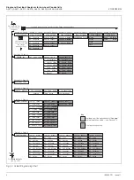
Page 6: ...als VIEW LOGBOOK VIEW CLOCK Date 05 02 04 Time 12 00 Use the Menu Key to scroll through the Menus CONFIG ALARMS Config Alarm 1 A1 Type A1 Assign A1 Failsafe A1 Action A1 Setpoint A1 Hysteresis A1 Delay Config Alarm 2 A2 Type A2 Assign A2 Failsafe A2 Action A2 Setpoint A2 Hysteresis A2 Delay A3 Assign A3 Failsafe A3 Action A3 Setpoint A3 Hysteresis A3 Delay Config Alarm 3 A3 Type Section 5 4 Page 3...

Page 7: ...rivative time Output Type Pulses Minute Cycle Time Output Range OR OR Power Recovery Power Rec Mode Default Output CONFIG OUTPUTS Config Output 1 AO1 Assign AO1 Range AO1 Span Value AO1 Zero Value AO1 Default O P AO1 Default Val Config Output 2 AO2 Assign AO2 Range AO2 Span Value AO2 Zero Value AO2 Default O P AO2 Default Val Config Output 3 AO3 Assign AO3 Range AO3 Span Value AO3 Zero Value AO3 D...

Page 8: ...between 0 and 100 Note Displayed only if Controller is set to PID see section 5 7 page 41 Control Set Point Conductivity value Control set point Use the and keys to adjust the control set point between 0 and 250 conductivity Note Displayed only if Controller is set to PID see section 5 7 page 41 Temperature Compensated Conductivity Value AX450 Analyzers Only Notes This frame is displayed only if A...

Page 9: ...zers Only Sensor A Sensor B Notes This frame is displayed only if Cond Units for either or both sensors is set to USP645 see section 5 3 page 21 If Cond Units for a sensor is set to USP645 Section 5 3 the displayed conductivity reading for that sensor is the temperature compensated value i e the value it would be at a sample temperature of 25ºC 77ºF Measured Temperature Sensor A Sensor B Note The ...

Page 10: ...wer display line followed by the result of the calculation Calculations performed are Difference A B Rejection 1 B A x 100 Passage B A x 100 Ratio A B Inferred pH Uses an algorithm to calculate the pH value of the solution inferred from its conductivity in the range 7 00 to 11 00 pH see appendix A 3 on page 75 for further information on inferred pH Note If the analyzer is used with a cation resin ...

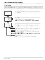
Page 11: ...l input analyzers only Sensor B Temperature Alarm 4 Set Point Dual input analyzers only Note Alarm 4 available only if option board fitted and analog features enabled see section 7 3 page 62 Alarm 5 Set Point Note Alarm 5 available only if option board fitted and analog features enabled see section 7 3 page 62 See Section 3 2 Enable Cals set to Yes Section 5 3 see section 4 1 page 17 Enable Cals s...

Page 12: ...urrent output shown as a percentage of full scale for the output range set in CONFIG OUPUTS see section 5 5 page 34 See Section 3 3 Enable Cals set to Yes Section 5 3 see section 4 1 page 17 Enable Cals set to No Section 5 3 and Alter Sec Code not set to zero Section 5 9 see section 5 1 page 19 Enable Cals set to No Section 5 3 and Alter Sec Code set to zero Section 5 9 see section 5 2 page 20 Adv...

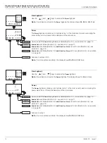
Page 13: ...r B input Option Board Note Displayed only if the option board is fitted Displays the optional features enabled in the Factory Settings page see section 7 3 page 62 See Section 3 4 Enable Cals set to Yes Section 5 3 see section 4 1 page 17 Enable Cals set to No Section 5 3 and Alter Sec Code not set to zero Section 5 9 see section 5 1 page 19 Enable Cals set to No Section 5 3 and Alter Sec Code se...

Page 14: ...n Section 5 10 see section 3 5 page 13 Operating Page option board not fitted see section 2 3 page 6 Enable Cals set to Yes Section 5 3 see section 4 1 page 17 Enable Cals set to No Section 5 3 and Alter Sec Code not set to zero Section 5 9 see section 5 1 page 19 Enable Cals set to No Section 5 3 and Alter Sec Code set to zero Section 5 9 see section 5 2 page 20 0 01 AX450 2000 Issue VIEW SOFTWAR...

Page 15: ...ore Entries Alarms The Alarms logbook contains up to 10 entries entry 1 is the most recent each comprising an alarm number alarm state On or Off and the date time of the occurrence Option board fitted and analog features enabled Section 7 3 see section 3 6 page 16 Enable Cals set to Yes Section 5 3 see section 4 1 page 17 Enable Cals set to No Section 5 3 and Alter Sec Code not set to zero Section...

Page 16: ...o more entries are stored the display shows No More Entries View Logbook Use the and keys to access the Power logbook Note If no entries are stored in the Power logbook the display shows No More Entries Power The Power logbook contains up to 2 entries entry 1 is the most recent each comprising the power state On or Off and the date time of the occurrence Option board fitted and analog features ena...

Page 17: ...or the temperature slope and temperature offset values for a temperature calibration together with the date time of the calibration Note If no more entries are stored the display shows No More Entries Option board fitted and analog features enabled Section 7 3 see section 3 6 page 16 Enable Cals set to Yes Section 5 3 see section 4 1 page 17 Enable Cals set to No Section 5 3 and Alter Sec Code not...

Page 18: ...on 7 3 page 62 Date Shows the current date Time Shows the current time Operating Page see section 2 3 page 6 Enable Cals set to Yes Section 5 3 see Section 4 1 Enable Cals set to No Section 5 3 and Alter Sec Code not set to zero Section 5 9 see section 5 1 page 19 Enable Cals set to No Section 5 3 and Alter Sec Code set to zero Section 5 9 see section 5 2 page 20 Date 05 02 04 VIEW CLOCK Time 12 0...

Page 19: ...n 0000 and 19999 to gain access to the sensor calibration pages If an incorrect value is entered access to the calibration pages is prevented and the display reverts to the SENSOR CAL frame Calibrate Sensor A Sensor B calibration dual input analyzers only is identical to Sensor A calibration Single input analyzers only return to main menu Alter Sec Code not set to zero Section 5 9 see section 5 1 ...

Page 20: ... temperature slope value within the range 0 200 to 1 500 until the measured temperature value is correct Temperature Offset Measured temperature value Temperature offset value Use the and keys to adjust the temperature offset value within the range 40 0 to 40 0ºC 40 0 to 104 0ºF until the measured temperature value is correct Sensor B calibration dual input analyzers only is identical to Sensor A ...

Page 21: ...frame is displayed only if Alter Sec Code is not set to zero see section 5 9 page 47 Enter the required code number between 0000 and 19999 to gain access to the configuation pages If an incorrect value is entered access to the configuation pages is prevented and the display reverts to the Operating Page see section 2 3 page 6 see section 5 2 page 20 SECURITY CODE 0000 CONFIG DISPLAY ...

Page 22: ...keys to select the sample temperature display units Set Up Display Backlight Backlight Use the and keys to select the required backlight option Auto On Backlight comes on at each button press and switches off one minute after the last button press Backlight is always on Return to main menu see section 5 3 page 21 CONFIG DISPLAY Set Language Temp Units Off Set Temp Units Deg F Deg C LED Backlight S...

Page 23: ...ROGRAMMING IM AX4CO Issue 11 21 5 3 Configure Sensors Configure Sensor A Sensor B configuration dual input analyzers only is identical to Sensor A configuration Single input analyzers only return to main menu Continued on next page Config Sensor A Cond CONFIG SENSORS Config Sensor B A Cond Units CONFIG SENSORS ...

Page 24: ...00 0 to 700 0 to 800 1 0 0 to 10 000 0 to 4 000 0 to 5 000 0 to 6 000 0 to 7 000 0 to 8 000 Table 5 1 Range Limits for Different Cell Constants K Conductivity Cell Constant K Conductivity Measuring Range 0 01 0 to 100 0μS cm 1 0 to 10 000μS m 1 0 05 0 to 500 0μS cm 1 0 to 10 000μS m 1 0 10 0 to 1 000μS cm 1 0 to 10 000μS m 1 0 to 100 0mS m 1 1 00 0 to 10 000μS cm 1 0 to 10 000μS m 1 0 to 10mS cm 1...

Page 25: ...r for injection WFI for US Pharmacopoeia USP applications Purified water for USP applications Temperature compensation for sample temperatures in the range 0 to 100ºC 0 to 212ºF This setting is suitable for the majority of applications Temperature compensation for sample temperatures in the range 0 to 200ºC 0 to 392ºF This setting is used only for special high temperature applications Continued on...

Page 26: ...xamples Cation exchanger in bed and outlet applications Degassed cation conductivity applications Temperature compensation based on the temperature coefficient of pure water containing trace caustic Example Inferred pH in caustic dosed waters applications Temperature compensation based on the temperature coefficient of pure water containing trace salts Examples General monitoring applications Mixe...

Page 27: ... 3 Also enables manual entry of a temperature coefficient see Temp Coeff frame on page 26 for applications where pure water contains an unknown impurity in which case the temperature coefficient must be calculated see appendix A 1 1 on page 74 Neutrl Temperature compensation based on the temperature coefficient of pure water containing trace neutral salts Acid Temperature compensation based on the...

Page 28: ... not yet been calculated set it to 2 ºC provisionally TDS Factor Note Displayed only if A Cond Units is set to TDS see page 22 The TDS factor must be programmed to suit the particular application see appendix A 2 on page 74 Enter the required TDS factor between 0 4 and 0 8 For salinity applications set the TDS factor to 0 6 TDS Units Note Displayed only if A Cond Units is set to TDS see page 22 Se...

Page 29: ...418 AX450 AX455 AX456 5 PROGRAMMING IM AX4CO Issue 11 27 Configure Sensor B dual input analyzers only Sensor B configuration is identical to Sensor A configuration Continued on next page Return to main menu Config Sensor B B Enable Cals Yes No CONFIG SENSORS Config Sensor B Signal Calc ...

Page 30: ...Range and B T Comp Range are set to Lo TC page 23 and A Temp Comp is set to NaOH and B Temp Comp is set to Acid pages 24 and 25 Inf pH NH3 NaCl Inf pH NH3 Calculates a pH value in the range 7 00 to 10 00 pH based on the type of chemical dosing and the conductivity readings Note Inf pH NH3 NaCl and Inf pH NH3 are available only if A Cond Units and B Cond Units are set to uS cm page 22 and A T Comp ...

Page 31: ...al Calc is set to Inf pH NH3 Inf pH NH3 NaCl or Inf pH NaOH Set the required after cation conductivity limit between 0 060 and 10 00 μS cm 1 Signal Calc set to Inf pH NH3 0 060 and 25 00 μS cm 1 Signal Calc set to Inf pH NH3 NaCl 1 000 and 100 0 μS cm 1 Signal Calc set to Inf pH NaOH Return to main menu See Section 5 4 uS cm 0 060 After Cat Limit CONFIG ALARMS CONFIG SENSORS Signal Calc ...

Page 32: ...rature and changes automatically with changes in sample temperature If the sample temperature is between the values given in the table the alarm set point is set to the value corresponding to the nearest lower temperature e g if the sample temperature is 29ºC 84 2ºF the alarm set point is set automatically to 1 3μS cm 1 Note The USP645 alarm type is available only on AX450 and AX455 analyzers and ...

Page 33: ... Signal Calc dual input analyzers only is set to any parameter other than No Calculation page 28 the selected parameter is displayed Pass Rej A B A B pH Signal Calc set to Passage Signal Calc set to Rejection Signal Calc set to Difference A B Signal Calc set to Ratio A B Signal Calc set to Inf pH NH3 Inf pH NH3 NaCl or Inf pH NaOH see appendix A 3 on page 75 for further information on inferred pH ...

Page 34: ... see Table 5 2 page 22 Alarm 1 Hysteresis A differential set point can be defined between 0 and 5 of the alarm set point value Set the required hysteresis in 0 1 increments See also Fig 5 1 to Fig 5 5 page 33 Alarm 1 Delay If an alarm condition occurs activation of the relays and LEDs can be delayed for a specified time period If the alarm clears within the period the alarm is not activated Set th...

Page 35: ... 2 High Failsafe Alarm with Hysteresis but no Delay Fig 5 3 High Failsafe Alarm with Hysteresis and Delay Relay Energized LED Off Relay De energized LED On Process Variable High Set Point Relay Energized LED Off Relay De energized LED On Process Variable Hysteresis High Set Point Relay Energized LED Off Relay De energized LED On Process Variable High Set Point Delay Hysteresis Fig 5 4 High Non Fai...

Page 36: ...sensor Temp A Temp B Temperature for the selected sensor Notes Sen B and Temp B are applicable only to dual input analyzers If Signal Calc dual input analyzers only is set to any parameter other than No Calculation page 28 the selected parameter is displayed Pass Rej A B A B pH Signal Calc set to Passage Signal Calc set to Rejection Signal Calc set to Difference A B Signal Calc set to Ratio A B Si...

Page 37: ... 3 Straight line between zero and span Bi linear see Fig 5 6 on page 39 Logarithmic 2 decades see Fig 5 7 on page 39 Logarithmic 3 decades see Fig 5 8 on page 40 Note The curve is fixed to Linear if a the analog output is assigned to temperature or b the analog output is assigned to Sensor A or Sensor B dual input analyzers only and Cond Units is set to M Ohms Section 5 3 Continued on next page AO...

Page 38: ... automatically Set Breakpoint X Value uS cm and Adjust are shown alternately on the upper display line Use the and keys to adjust the displayed reading to the required breakpoint conductivity value This is Point B in Fig 5 6 Current value at which the breakpoint occurs Note Applicable only if the Curve parameter is set to Bi Lin see previous page Set Breakpoint Y Value Conductivity value at which ...

Page 39: ...22 00mA Output 2 configuration and Outputs 3 and 4 if option board fitted and analog features enabled see section 7 3 page 62 is identical to Output 1 configuration Option board fitted and analog features enabled Section 7 3 see section 5 7 page 41 Option board fitted and Serial Communications feature enabled Section 7 3 see Supplementary Manual PROFIBUS Datalink Description IM PROBUS Single input...

Page 40: ...nductivity Range Maximum Conductivity Range 0 01 0 to 0 1μS cm 1 0 to 10 00μS m 1 0 to 100 0μS cm 1 0 to 10 000μS m 1 0 05 0 to 0 5μS cm 1 0 to 50 00μS m 1 0 to 500 0μS cm 1 0 to 10 000μS m 1 0 10 0 to 1μS cm 1 0 to 100μS m 1 0 to 0 1mS m 1 0 to 1 000μS cm 1 0 to 10 000μS m 1 0 to 100 0mS m 1 1 00 0 to 10μS cm 1 0 tpo 1 000μS m 1 0 to 0 01mS cm 1 0 to 1mS m 1 0 to 10 000μS cm 1 0 to 10 000μS m 1 0...

Page 41: ...i Linear Output 5 6 2 Logarithmic Output 2 decade Fig 5 6 Bi Linear Output Fig 5 7 Logarithmic Output 2 Decade Conductivity Measurement Analog Output mA B C A 0 2 4 6 8 10 12 14 16 18 20 0 10 20 30 40 50 60 70 80 90 100 Span Value Zero Value Breakpoint D Conductivity Measurement shown as of Analog Output Span Value Analog Output 1 100 10 0 10 20 30 40 50 60 70 80 90 100 ...

Page 42: ...X411 AX413 AX416 AX418 AX450 AX455 AX456 5 PROGRAMMING 40 IM AX4CO Issue 11 5 6 3 Logarithmic Output 3 decade Fig 5 8 Logarithmic Output 3 Decade 0 1 1 10 100 Conductivity Measurement shown as of Analog Output Span Value Analog Output 0 10 20 30 40 50 60 70 80 90 100 ...

Page 43: ...ed see section 5 8 page 42 Dual input analyzer and option board not fitted see section 5 9 page 47 Date Format Select the required date format Date Set the date in the format selected above Press to move between the day month and year fields Use the and keys to adjust each field Time Set the time in the form hh mm Press to move between the hours and minutes fields Use the and keys to adjust each f...

Page 44: ...control is applicable only to single input analyzers Before configuring the PID controller refer to see appendix B on page 78 for further information Controller Type Select the controller type Off PID Disables the controller Single PID controller Controller set to PID see section 5 8 1 page 43 See Section 5 9 CONFIG CONTROL Controller PID Controller PID Off CONFIG SECURITY ...

Page 45: ...nds in 1 second increments Set to OFF to disable integral action time Derivative Action Time Set the derivative action time between 0 1 and 999 9 seconds in 0 1 second increments Set to OFF to disable derivative action time Output Type Set the required output type Time Analog Pulse Time proportioning relay 1 Analog output analog output 1 Pulse frequency relay 1 Output Type set to Time continued on...

Page 46: ...lculated using the following equation on time Set the cycle time between 1 0 and 300 0 seconds in 0 1 second increments see appendix B on page 78 Fig B 4 Mode C Note Changes to the cycle time do not take effect until the start of a new cycle See Section 5 8 2 See Section 5 9 Analog Output Set the analog current output range See Section 5 8 2 See Section 5 9 Cycle Time 10 0Secs Power Recovery Outpu...

Page 47: ...en the frequency needs to be increased The actual number of pulses per minute is calculated using the following equation Actual pulses per minute Set the pulse frequency between 1 and 120 pulses per minute in 1 pulse per minute increments Control Output Pulse Frequency Output Minute 1 10 50 120 0 0 0 0 0 25 0 25 2 5 12 5 30 50 0 50 5 0 25 60 75 0 75 7 5 37 5 90 100 1 00 10 0 50 120 Note If the pul...

Page 48: ...to Auto irrespective of its setting prior to the power failure Control Mode is set to Manual irrespective of its setting prior to the power failure Control Output Section 2 3 is set to the level set in the Default Output frame below Control Mode and Control Output are set to the same state as that set prior to the power failure Default Output Set the default output required after Power Failure Rec...

Page 49: ... to main menu Option board fitted and analog features enabled Section 7 3 see section 5 10 page 47 Alter Sec Code 00000 Alter Cal Code 00000 CONFIG SECURITY CONFIG LOGBOOK CONFIG SECURITY Alter Sec Code Note The Configure Logbook function is available only if the option board is fitted and analog features enabled see section 7 3 page 62 Configure Logbook Use the and keys to to set the logbook On o...

Page 50: ...adjust the displayed theoretical output current value to give the output required See Section 7 3 Test remaining outputs Maintenance Hold Outputs Enables the relay action and analog outputs to be maintained Auto On Off Changes in relay action and analog outputs are disabled during sensor calibration Changes in relay action and analog outputs are disabled Changes in relay action and analog outputs ...

Page 51: ...a configuration is to be loaded or saved Note If No is selected pressing the key has no effect Return to main menu See Section 7 3 Load User Factory Configuration Note Applicable only if Load Save Config is set to Yes Factory Config Save User Config Load User Config resets all the parameters in the Configuration Pages to the Company Standard saves the current configuration into memory reads the sa...

Page 52: ...nt away from harmful vapours and or dripping fluids Where possible mount the analyzer at eye level to allow an unrestricted view of the front panel displays and controls Fig 6 1 Siting Requirements C Within Environmental Limits B Within Temperature Limits A Maximum Distance Between Analyzer and Sensor Conductivity Sensor Maximum Distance 50m 137 5 ft cell constant 0 1 100m 275 ft cell constant 0 1...

Page 53: ... mounting 175 6 9 150 5 9 25 210 8 23 192 7 56 96 3 76 R10 0 4 192 7 56 Ø 6 5 0 0 2 6 Dimensions in mm in Fixing Centers Fixing Centers 94 3 7 B Pipe mounting Position U bolts on pipe Position plate over U bolts Secure transmitter to mounting plate Secure plate A Wall mounting Mark fixing centres see Fig 6 2 Drill suitable holes 1 2 3 4 1 2 3 61 2 3 8 OD Vertical or Horizontal Post Secure instrume...

Page 54: ...n mm in 96 3 78 96 3 78 5 40 0 2 91 60 3 6 137 50 5 41 25 0 98 Panel Cut out 0 8 0 92 3 62 0 03 0 0 8 0 92 3 62 0 03 0 Insert the instrument into the panel cut out Secure the analyzer by tightening the panel clamp retaining screws see Note below Loosen the retaining screw on each panel clamp Remove the panel clamp and anchors from the instrument case Cut a hole in the panel see Fig 6 4 for dimensi...

Page 55: ...ipment with no accessible live parts The relay contacts are voltage free and must be appropriately connected in series with the power supply and the alarm control device which they are to actuate Ensure that the contact rating is not exceeded Refer also to Section 6 3 1 for relay contact protection details when the relays are to be used for switching loads Do not exceed the maximum load specificat...

Page 56: ...esistor capacitor network depends on the load current and inductance that is switched Initially fit a 100R 0 022μF RC suppressor unit part no B9303 as shown in Fig 6 6A If the analyzer malfunctions locks up display goes blank resets etc the value of the RC network is too low for suppression and an alternative value must be used If the correct value cannot be obtained contact the manufacturer of th...

Page 57: ... Knockouts Wall Pipe mount Analyzer 5 Place the blade of a small flat bladed screwdriver into the knockout groove and tap the screwdriver smartly to remove the knockout see Note below Smooth the edges of the hole with a small round or half round file Fit an O ring seal to the the cable gland Insert the cable gland into the hole in the analyzer case from the outside Secure the cable gland with the ...

Page 58: ... INSTALLATION 56 IM AX4CO Issue 11 6 4 Wall Pipe mount Analyzer Connections 6 4 1 Access to Terminals Fig 6 8 Access to Terminals Wall Pipe mount Analyzer Terminal Block A Terminal Block B Terminal Block C Option Board Case Earth Ground Stud Release the four captive screws and remove the terminal cover plate ...

Page 59: ...er B2 B10 Temperature Compensator Third Lead B3 B11 Temperature Compensator B4 B12 Screen B5 B13 Cell Cell Electrode B6 B14 Cell Earth Electrode see Note below B7 B15 Not Used B8 B16 Not Used Refer also to Section 6 6 for ABB UK and US Sensor Systems Connections C1 Not used C2 Not used C3 C4 C5 C6 Not used C7 C C8 NC Relay 4 C9 NO C10 C C11 NC Relay 5 C12 NO C13 Analog Output 3 C14 C15 Analog Outp...

Page 60: ...11 AX413 AX416 AX418 AX450 AX455 AX456 6 INSTALLATION 58 IM AX4CO Issue 11 6 5 Panel mount Analyzer Connections 6 5 1 Access to Terminals Fig 6 10 Access to Terminals Panel mount Analyzers Terminal Block C Option Board Terminal Block B Terminal Block A Earth Ground Stud ...

Page 61: ...e Compensator Common Link B9 to B10 and B1 to B2 if Dual Input Analyzer B2 B10 Temperature Compensator Third Lead B3 B11 Temperature Compensator B4 B12 Screen B5 B13 Cell Cell Electrode B6 B14 Cell Earth Electrode see Note below B7 B15 Not Used B8 B16 Not Used L Line N Neutral E Connect supply earth ground to stud on case A4 C A5 NC Relay 1 A6 NO A7 C A8 NC Relay 2 A9 NO A10 C A11 NC Relay 3 see N...

Page 62: ...B8 B16 Not Used Not Used Not Used Table 6 1 Conductivity Cell Connections Cable Detached Models 2045 and 2077 and Models 2078 and 2085 with Plug and Socket Terminal Block B Sensor B Sensor A Cable Colors B1 B9 Green B2 B10 Link B2 to B1 and Link B10 to B9 if Dual Input Analyzer B3 B11 Yellow B4 B12 B5 B13 Red B6 B14 Blue B7 B15 Not Used B8 B16 Not Used Table 6 2 Conductivity Cell Connections Cable...

Page 63: ... the conductivity cell Connect the decade box resistance earth to B4 c Connect one terminal of the 0 to 1kΩ decade resistance box to B1 and the other terminal to B3 to simulate the Pt100 Pt1000 3 Connect the milliammeter to the analog output terminals 4 Switch on the supply and allow ten minutes for the circuits to stabilize 5 Select the FACTORY SETTINGS page and carry out Section 7 3 Note The ana...

Page 64: ... Zero O C A Res Span 20R A Self Checking A T Zero 100R A T Span 150R Cal Sensor B B Res Zero O C B Res Span 2K0 B Res Zero O C B Res Span 20R B Self Checking B T Zero 100R B T Span 150R Cal Output 1 O1 Adjust 4mA O1 Adjust 20mA To OPERATING PAGE A T Zero 1K0 B T Zero 1K0 A T Span 1K5 B T Span 1K5 Dual conductivity only Key Alter Fact Code Cal Output 3 Cal Output 4 O3 Adjust 4mA O4 Adjust 4mA O3 Ad...

Page 65: ...the display lines for sensor calibration are shown only as examples the actual values obtained will differ Sensor B calibration dual input analyzers only is identical to Sensor A calibration Single input analyzers only see page 66 Operating Page see section 2 3 page 6 Calibrate Input for Sensor A If calibration is required select Yes otherwise select No Note To abort calibration press the key agai...

Page 66: ...al is within range the lower 7 segment display shows the same value and Calib is displayed to indicate that calibration is in progress Resistance Span 2k0 Set the cell simulator to 2kΩ The display advances automatically to the next step once a stable and valid value is recorded Resistance Zero Open Circuit Open circuit the cell simulator The display advances automatically to the next step once a s...

Page 67: ...ically to the next step once a stable and valid value is recorded Temperature Zero 1k0 Set the temperature simulator to 1kΩ The display advances automatically to the next step once a stable and valid value is recorded Temperature Span 1k5 Set the temperature simulator to 1 5kΩ The display returns automatically to Cal Sensor A once a stable and valid value is recorded Abort Calibration Select Yes o...

Page 68: ... 5 does not affect the reading See below Operating Page see section 2 3 page 6 Calibrate Output 2 Note Output 2 calibration is identical to Output 1 calibration Option board fitted and analog features enabled continued on next page Option board fitted additional features disabled continued on next page Option board not fitted continued on next page Option board fitted and analog features enabled c...

Page 69: ... of the available features If an incorrect selection is made the software menus and frames associated with that option are displayed in the Operating and Configuration pages but the features do not work Use the and keys to enable the features for the type of option board s fitted Analog Pb Dp Analog Pb Dp Analog features enabled comprising two additional analog outputs two additional alarm relays ...

Page 70: ... b check the cable connections and condition If the response for both checks is correct replace the conductivity cell Error Message Possible Cause A FAULTY Pt100 A FAULTY Pt1000 Temperature compensator associated connections for Sensor A are either open circuit or short circuit B FAULTY Pt100 B FAULTY Pt1000 Temperature compensator associated connections for Sensor B are either open circuit or sho...

Page 71: ...analyzer displays the correct values as set on the resistance box see Table 8 3 Incorrect readings usually indicate an electrical calibration problem Re calibrate the analyzer as detailed in Section 7 3 Temperature Input Resistance Ω ºC ºF Pt100 Pt1000 0 32 100 00 1000 0 10 50 103 90 1039 0 20 68 107 79 1077 9 25 77 109 73 1097 3 30 86 111 67 1116 7 40 104 115 54 1155 4 50 122 119 40 1194 0 60 140...

Page 72: ...000 ppm Inferred pH 7 0 to 10 0pH NH3 dosed systems 7 0 to 11 0pH NaOH dosed systems pH calculation according to the appendix in the VGB directive 450L 1988 pH Redox ORP AX416 Inputs pH or mV input and solution earth Temperature sensor Pt100 Pt1000 or Balco 3k Enables connection to glass or enamel pH and reference sensors and Redox ORP sensors Input resistance Glass 1 x 10¹³Ω Reference 1 x 10¹³Ω R...

Page 73: ...to earth ground Analog Outputs Number of current outputs fully isolated Two supplied as standard or four with option board fitted Output range 0 to 10mA 0 to 20mA or 4 to 20mA Analog output programmable to any value between 0 and 22mA to indicate system failure Accuracy 0 25 FSD 0 5 of reading whichever is the greater Resolution 0 1 at 10mA 0 05 at 20mA Maximum load resistance 750Ω at 20mA Configu...

Page 74: ... 7 in deep Weight 1kg 2 2 lb Panel mount versions IP66 NEMA4X front only Dimensions 96mm x 96mm x 162mm deep 3 78 in x 3 78 in x 6 38 in deep Weight 0 6kg 1 32 lb Cable Entry Types Standard 5 or 7 x M20 cable glands North American 7 x knockouts suitable for 1 2 in Hubble gland Power Supply Voltage requirements 85 to 265V AC 50 60 Hz 24V AC or 12 to 30V DC optional Power consumption 10VA Insulation...

Page 75: ...on is due to a change in impurity level or in temperature For conductivity levels above 1μS cm 1 the generally accepted expression relating conductivity and temperature is Gt G25 1 t 25 Where Gt conductivity at the temperature tºC G25 conductivity at the standard temperature 25ºC temperature coefficient per ºC At conductivities between 1μS cm 1 and 1 000μS cm 1 lies generally between 0 015 ºC and ...

Page 76: ...ly dependent on the properties of the solution being measured In simple solutions where only one electrolyte is present the conductivity TDS ratio can be ascertained easily e g 0 5 in the case of sodium chloride However in complex solutions where more than one electrolyte is present the ratio is not calculated easily and can be reliably determined only by laboratory testing e g precipitation and w...

Page 77: ...onductivity inputs must be configured as μS cm 1 in order to calculate inferred pH Warning The calculation of inferred pH relies on the strict control of chemical conditions within the NH3 NH3 NaCl or NaOH dosed sample Contamination with chemical substances other than those with which the sample is dosed introduces significant errors in the inferred pH calculated value and in the worse case invali...

Page 78: ...here there are low concentrations of ionic impurities present in addition to the volatile alkaline agent e g sodium chloride ammonia In this case the exchange of ammonium and sodium ions within the cation column releases water and hydrochloric acid The sodium chloride impurity produces a conductivity after the column that is higher than the conductivity before The dual input analyzer when used to ...

Page 79: ...e BC the before column reading AC the after column reading F molar conductivity change for the alkaline agent 243μS cm 1 per mmol l for sodium hydroxide The maximum after cation conductivity value is programmable between 1 00 and 100 0μS cm 1 dependent on local conditions After cation values above this level generate an AFTER CAT HIGH error message and before cation values above 100 0μS cm 1 gener...

Page 80: ...system using three term PID control with a local set point B 1 1 Reverse Acting Single PID Control Reverse acting control is used when the process conductivity is less than the required output conductivity Fig B 1 Single PID Controller Fig B 2 Reverse Acting Single PID Control Process Variable Control Set Point Manual Output PID Output Output 1 PID Control Loop Control Output 100 0 0 50 100 Revers...

Page 81: ...e PID Control Direct acting control is used when the process conductivity is greater than the required output conductivity B 2 Ouput Assignment The output signal is assignable to either relay 1 Time or Pulse output type or analog output 1 Analog output type Fig B 3 Direct Acting Single PID Control Control Output 100 0 0 50 100 Direct Acting Process Variable Range ...

Page 82: ...o PID see Section 5 7 2 Select the PID Controller page and set the following Proportional Band 100 Integral Time 0 off see Section 5 8 1 Derivative Time 0 off 3 Reduce the Proportional Band by 20 increments and observe the response Continue until the process cycles continuously without reaching a stable condition i e a sustained oscillation with constant amplitude as shown in Mode C This is the cr...

Page 83: ...umentation pH Conductivity and Dissolved Oxygen Transmitters and Sensors Ammonia Nitrate Phosphate Silica Sodium Chloride Fluoride Dissolved Oxygen and Hydrazine Analyzers Zirconia Oxygen Analyzers Katharometers Hydrogen Purity and Purge gas Monitors Thermal Conductivity Customer Support We provide a comprehensive after sales service via a Worldwide Service Organization Contact one of the followin...

Page 84: ...uct improvement and the right is reserved to modify the information contained herein without notice Printed in UK 02 07 ABB 2007 ABB Limited Oldends Lane Stonehouse Gloucestershire GL10 3TA UK Tel 44 0 1453 826661 Fax 44 0 1453 829671 ABB Inc Analytical Instruments 9716 S Virginia St Ste E Reno Nevada 89521 USA Tel 1 775 850 4800 Fax 1 775 850 4808 ...

Reviews: