Single and Dual Input Analyzers for Low Level Conductivity
AX410, AX411, AX413, AX416, AX418, AX450, AX455 & AX456
3 OPERATOR VIEWS
IM/AX4CO Issue 11
9
3 OPERATOR VIEWS
3.1 View Set Points
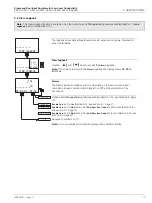
View Set Points
This page shows alarm set points. The value of each of the set points is shown,
together with the name of the parameter it's assigned to.
Alarm assignments, set point values and relay/LED actions are programmable - see
section 5.4, page 30. Those shown in the following frames are examples only.
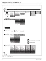
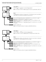
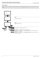
Sensor A (Conductivity), Alarm 1 Set Point
Sensor A (Temperature), Alarm 2 Set Point
Sensor B (Conductivity), Alarm 3 Set Point
- Dual input analyzers only
Sensor B (Temperature), Alarm 4 Set Point
- Dual input analyzers only
Note.
Alarm 4 available only if option board fitted
and
analog features enabled - see
Alarm 5 Set Point
Note.
Alarm 5 available only if option board fitted
and
analog features enabled - see
See Section 3.2.
Enable Cals.
set to
Yes
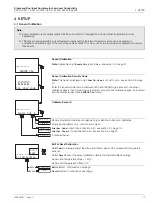
(Section 5.3) - see section 4.1, page 17.
Enable Cals.
set to
No
(Section 5.3)
and
Alter Sec. Code
not set to zero (Section 5.9) -
Enable Cals.
set to
No
(Section 5.3)
and
Alter Sec. Code
set to zero (Section 5.9) - see
8.300
uS/cm
A1: Setpoint
Sen.A
Temp.A
VIEW SETPOINTS
-----
35.0
Deg.C
A2: Setpoint
Sen.B
3.500
uS/cm
A3: Setpoint
Temp.B
55.0
Deg.C
A4: Setpoint
-----
Off
A5: Setpoint
VIEW OUTPUTS
SENSOR CAL.
CONFIG. DISPLAY
SECURITY CODE
VIEW SETPOINTS


