Single and Dual Input Analyzers for Low Level Conductivity
AX410, AX411, AX413, AX416, AX418, AX450, AX455 & AX456
5 PROGRAMMING
30
IM/AX4CO Issue 11
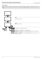
5.4 Configure Alarms
Configure Alarm 1
Alarm 2 and 3 configuration (and Alarms 4 and 5 if option board fitted
and
analog
features enabled - see section 7.3, page 62) is identical to Alarm 1.
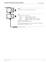
Alarm 1 Type
Select the type of alarm required:
Off
-
The alarm is disabled, the alarm LED is off and the relay is
de-energized at all times.
Alarm
-
The analyzer is configured using the Assign parameter (see next
page) to generate an alarm in response to a specified sensor
reading.
Status
-
An alarm is generated if either a power failure or a condition
occurs that causes any of the error messages in Table 8.1 (page
68) to be displayed.
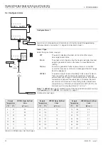
USP645
-
The alarm set point is set automatically to the value in Table 5.3
that corresponds with the sample temperature and changes
automatically with changes in sample temperature. If the sample
temperature is between the values given in the table, the alarm
set point is set to the value corresponding to the nearest lower
temperature, e.g. if the sample temperature is 29ºC (84.2ºF), the
alarm set point is set automatically to 1.3
μ
S cm
-1
.
Note.
The
USP645
alarm type is available only on AX450 and AX455 analyzers and only
if
A: Cond.Units
is set to
USP645
Continued on next page.
Sample
Temperature
USP645 Alarm Set Point
Value
Sample
Temperature
USP645 Alarm Set Point
Value
Sample
Temperature
USP645 Alarm Set Point
Value
(ºC)
(ºF)
(µS cm
-1
)
(ºC)
(ºF)
(µS cm
-1
)
(ºC)
(ºF)
(µS cm
-1
)
0
32
0.6
35
95
1.5
70
158
2.5
5
41
0.8
40
104
1.7
75
167
2.7
10
50
0.9
45
113
1.8
80
176
2.7
15
59
1.0
50
122
1.9
85
185
2.7
20
68
1.1
55
131
2.1
90
194
2.7
25
77
1.3
60
140
2.2
95
203
2.9
30
86
1.4
65
149
2.4
100
212
3.1
Table 5.3 USP645 Alarm Set Point Values
Config. Alarm 1
-----
A1: Type
-----
Off
CONFIG. ALARMS
-----
Off
Alarm
Status
USP645
A1: Assign
Config. Alarm 2
Config. Alarm 1
Off
or
Status
Alarm
or
USP645

