Single and Dual Input Analyzers for Low Level Conductivity
AX410, AX411, AX413, AX416, AX418, AX450, AX455 & AX456
2 OPERATION
6
IM/AX4CO Issue 11
2.3 Operating Page
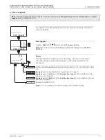
2.3.1 Single Input Conductivity
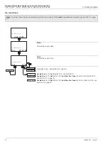
Measured Values
Conductivity.
Temperature.
Notes.
•
The displayed conductivity and temperature readings are the actual measured
values of the sample.
•
AX450 analyzers only - if
A: Cond.Units
is set to
USP645
(Section 5.3), the
displayed conductivity reading is the uncompensated conductivity value of the
sample, i.e. its value at the displayed temperature.
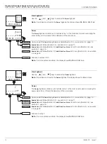
Control Mode
Conductivity value.
Control mode.
Use the
and
keys to switch between manual (
Manual
) and automatic (
Auto
)
control.
Note.
Displayed only if
Controller
is set to
PID
Control Output
Conductivity value.
Control output (%), manual (
Man
) or automatic (
Auto
).
When
Control Mode
is set to
Manual
(see above), use the
and
keys to
adjust the control output between 0 and 100%.
Note.
Displayed only if
Controller
is set to
PID
Control Set Point
Conductivity value.
Control set point.
Use the
and
keys to adjust the control set point between 0 and 250%
conductivity.
Note. Displayed only if
Controller
is set to
PID
Temperature Compensated Conductivity Value
- AX450 Analyzers Only
Notes.
•
This frame is displayed only if
A: Cond.Units
is set to
USP645
•
The displayed reading is the temperature compensated conductivity value i.e. the
value it would be at a sample temperature of 25ºC (77ºF).
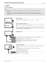
Enable Cals.
set to
Yes
(Section 5.3) - see section 4.1, page 17.
Enable Cals.
set to
No
(Section 5.3)
and
Alter Sec. Code
not set to zero (Section 5.9) -
Enable Cals.
set to
No
(Section 5.3)
and
Alter Sec. Code
set to zero (Section 5.9) - see
Conductivity
0.883
uS/cm
24.8
Deg.C
@ 25 Deg.C
0.886
uS/cm
VIEW SETPOINTS
SENSOR CAL.
CONFIG. DISPLAY
SECURITY CODE
Conductivity
Control Mode
uS/cm
Manual
0.883
----
Setpoint 90.0
uS/cm
% Man.
0.883
60.0
Control Setpoint
uS/cm
1.000
%Sat
150.0


