40
…6
INSTALLATION
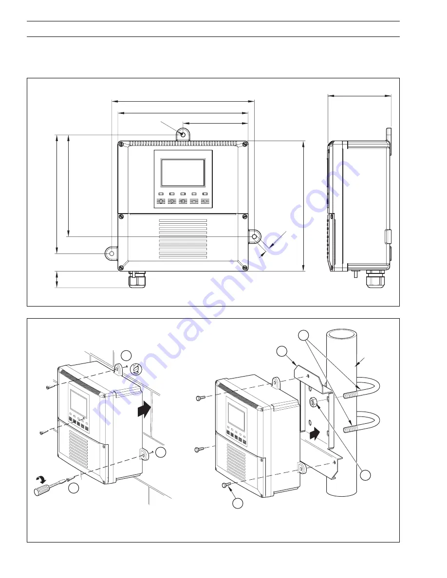
175 (6.9)
150 (5.9)
25
210 (8.23)
192 (7.56)
96 (3.76)
R10
(0
.4)
192 (7.56)
Ø
6.50 (0.26)
Dimensions in mm (in.)
Fixing Centers
Fixing Centers
94 (3.7)
Fig. 6.2 Overall Dimensions
B – Pipe-mounting
Position 'U' bolts on pipe
Position plate over 'U' bolts
Secure transmitter to mounting plate
Secure plate
A – Wall-mounting
Mark fixing centres
(see Fig. 6.2)
Drill suitable
holes
1
2
3
4
1
2
3
61 (2
3
/
8
) OD
Vertical or
Horizontal
Post
Secure instrument to
wall using
suitable fixings
Fig. 6.3 Wall-/Pipe-mounting
6.2
Mounting
6.2.1
Wall-/Pipe-mount Analyzers – Figs. 6.2 and 6.3
Summary of Contents for AX418
Page 66: ...64 NOTES ...


